IN-E-HyFlex-V4_10
Rotronic AG
Bassersdorf, Switzerland
Document code Unit
Instruction Manual
Document Type
HygroFlex transmitter version 4: instruction
manual
Document title
Page 27 of 61
© 2006; Rotronic AG IN-E-HyFlex-V2_10.doc
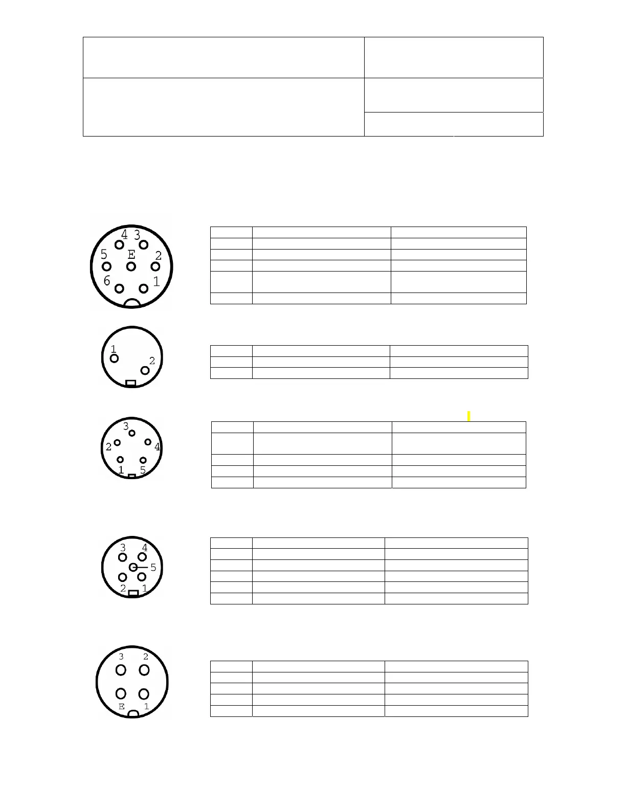
6.6 Connector plate connectors - pin-out diagrams
Note: the contact side of the female connector is the same as the solder side of the matching male connector.
Probe 1
TUCHEL T7 (7-pin female shown from contact side)
Pin # Function Pin# on PCB connector J2
E GND 3
1 Temperature – analog (+) 1
3 DIO (digital) 4
5 + 5 or +15 VDC ±0.5 VDC,
jumper-selectable, B19 / B20)
5
6 Humidity – analog (+) 2
Test Connector (2-pin female shown from contact side)
Pin # Function Pin# on PCB connector J4
1 DIO (digital) 2
2 GND 1
Probe 2 (5-pin female shown from contact side)
optional
Pin # Function Pin# on PCB connector J3
2 + 5 or +15 VDC ±0.5 VDC,
jumper-selectable, B19 / B20)
4
3 GND 2
4 DIO (digital) 3
5 Analog (+) 1
RS232 / RS485 (5-pin female shown from contact side)
Pin # Function Pin# on PCB connector J5
1 TXD 5
2 RXD 4
3 GND 3
4 RI + 2
5 RI - 1
Analog Outputs (4-pin female shown from contact side)
optional
Pin # Function Pin# on PCB connector
1 Output 1 (+) 1
2 Output 2 (+) 2
3 Output 3 (+) 3
4 GND 4