IN-E-HyFlex-V4_10
Rotronic AG
Bassersdorf, Switzerland
Document code Unit
Instruction Manual
Document Type
HygroFlex transmitter version 4: instruction
manual
Document title
Page 28 of 61
© 2006; Rotronic AG IN-E-HyFlex-V2_10.doc
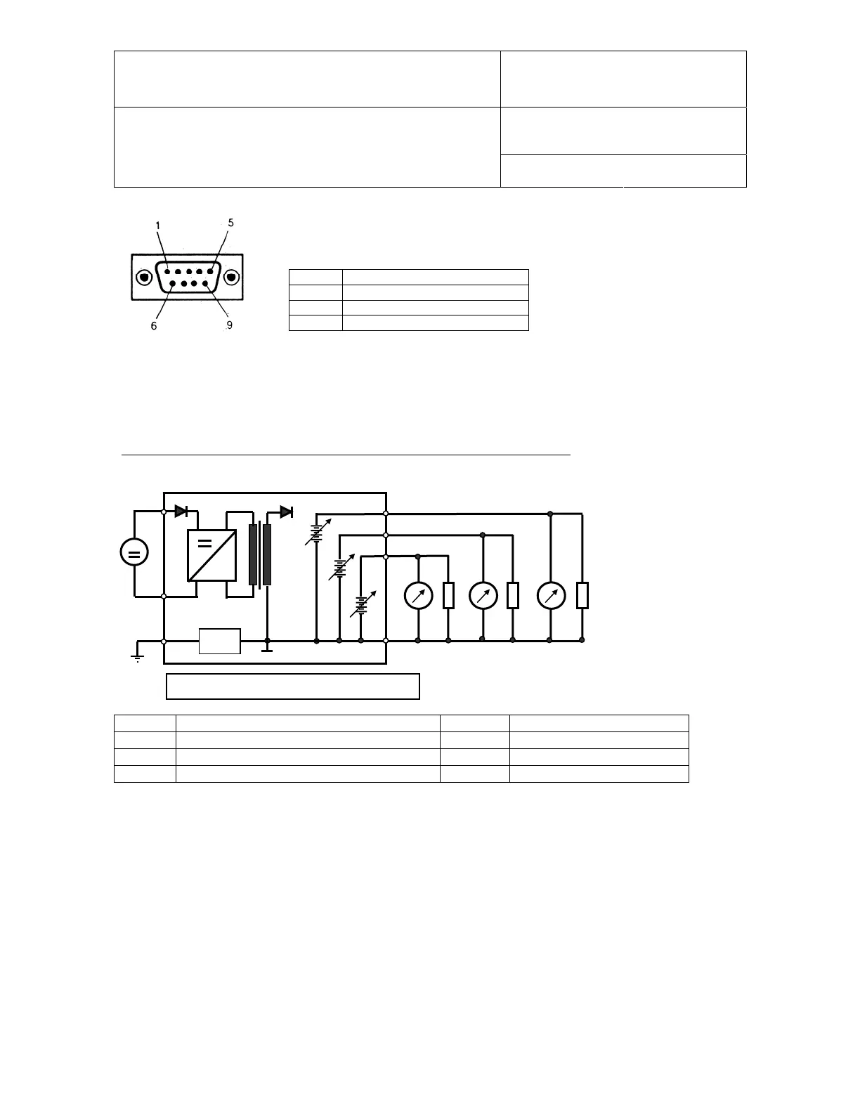
RS232 connection (DB9 female connecting to a PC or terminal server)
Viewed opposite from solder side
Pin # Function
2 RX
3 TX
5 GND
6.7 Electrical diagrams (analog outputs)
Before making the electrical connections, be sure to correctly identify each connector and terminal.
Applying power to any of the input or output terminals can severely damage the transmitter.
12 to 35 VDC or 12 to 24 VAC supply voltage and voltage output signals
TB1 TB2
R
L
R
L
R
L
~
~
B18
~
1
3
1
2
4
3
2
1) minimum load:
1000 ohm
Solder
ad B18: see
a
e 31
TB1 (2) 12…35 VDC (+) or 12…24 VAC neutral TB2 (1) Relative humidity (+)
TB1 (1) 12…35 VDC (-) or 12…24 VAC Ph TB2 (2) Temperature (+)
TB1 (3) Ground TB2 (3) Calculated Parameter (+)
TB2 (4) Common (-)
If so desired, close solder pad B18 (next to TB1) to connect signal ground and terminal 3 of the
power terminal block TB1.