IN-E-HyFlex-V4_10
Rotronic AG
Bassersdorf, Switzerland
Document code Unit
Instruction Manual
Document Type
HygroFlex transmitter version 4: instruction
manual
Document title
Page 29 of 61
© 2006; Rotronic AG IN-E-HyFlex-V2_10.doc
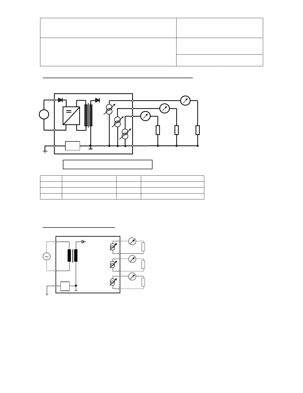
90…264 VAC with optional power module and current output signals
TB1 TB2
R
L
R
L
R
L
1) maximum load :
500 ohm
wiring included.
~
~
B18
~
3
1
2
4
3
2
1
Solder
ad B18: see
a
e 31
TB1 (2) 90…264 VAC Neutral TB2 (1) Relative humidity (+)
TB1 (1) Phase TB2 (2) Temperature (+)
TB1 (3) Ground TB2 (3) Calculated Parameter (+)
TB2 (4) Common (-)
If so desired, close solder pad B18 (next to TB1) to connect signal ground and terminal 3 of the
power terminal block TB1.
Floating Current Outputs (option)
R
L
1) maximum load : 500 ohm, wiring
R
L
R
L
B18
Solder pad B18: see page 24