IN-E-HyFlex-V4_10
Rotronic AG
Bassersdorf, Switzerland
Document code Unit
Instruction Manual
Document Type
HygroFlex transmitter version 4: instruction
manual
Document title
Page 22 of 61
© 2006; Rotronic AG IN-E-HyFlex-V2_10.doc
Note: disconnecting and reconnecting the ribbon cable while the transmitter is powered may cause
the display to remain blank. In that case, un-power and power again the transmitter.
5.5 Probe installation guidelines
Connect the probe to probe input 1 (main probe input). Except for probe model IW (area
monitoring); probes are connected to the HygroFlex by means of a cable (attached to the probe).
Do not remove the dust filter or slotted cap from the probe. Both sensors can easily be damaged
when not protected. For best results, please observe the following guidelines:
- Install the probe at a location where humidity, temperature and pressure conditions are
representative of the environment or process to be measured. Avoid the following: (a) Close
proximity of the probe to a heating element, a cooling coil, a cold or hot wall, direct exposure to
sun rays, etc. (b) Close proximity of the probe to a steam injector, humidifier, direct exposure to
precipitation, etc. (c) Unstable pressure conditions resulting from excessive air turbulence.
- If possible, choose a location that provides good air movement at the probe: air velocity of at
least 1 meter/second (200 ft/ minute) facilitates adaptation of the probe to changing
temperature.
- When installing the probe through a wall, immerse as much of the probe as possible in the
environment to be measured.
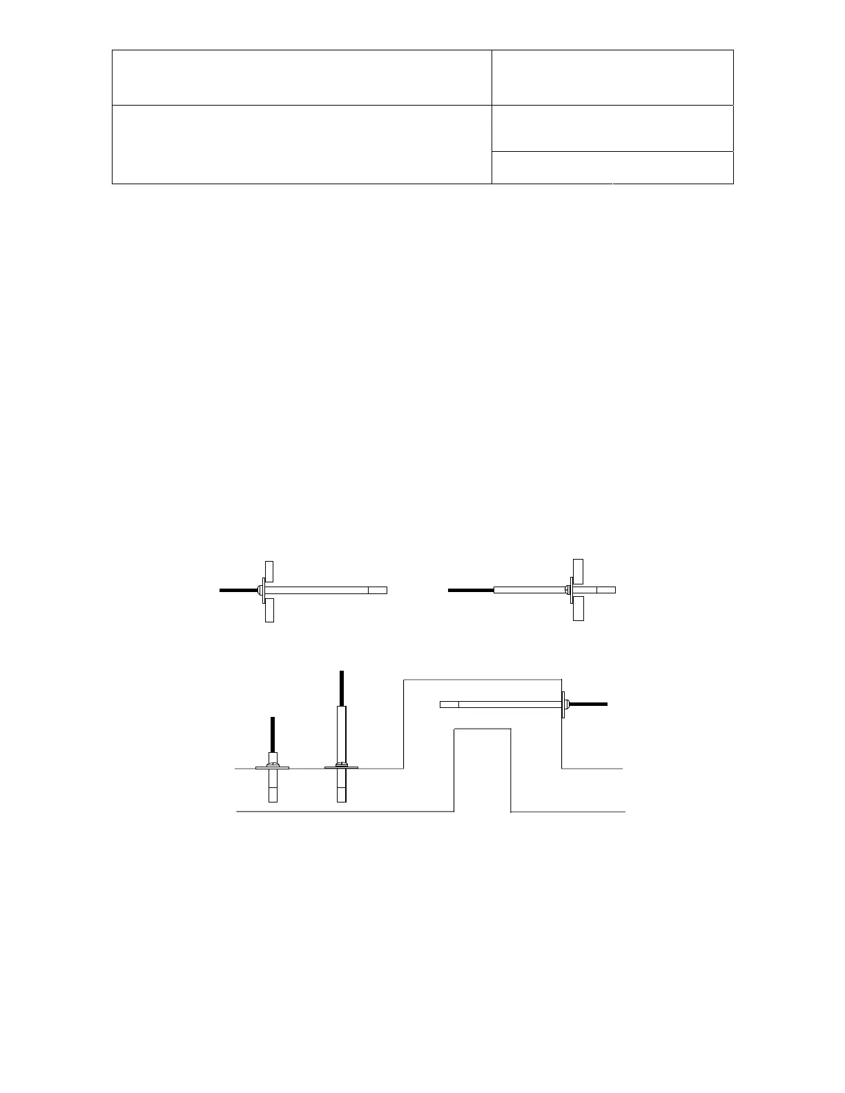
OK
NG
NG
Small Diameter Duct
Short Probe
OK
NG
9 to 9.5" immersion
Position the probe so as to prevent the accumulation of condensation water at the level of the
sensor leads. Install the probe so that the probe tip is looking downward. If this is not possible,
install the probe horizontally.
Depending on the probe model, a probe holder (mounting flange with a compression fitting) can
facilitate installation through a wall.
Future maintenance can be made easier by providing next to the probe a calibration access orifice.
During maintenance, this permits the insertion of a reference probe (calibrator).The calibration
access orifice should have the same size as the orifice used to install the probe and can be
equipped with a probe holder.