IN-E-HyFlex-V4_10
Rotronic AG
Bassersdorf, Switzerland
Document code Unit
Instruction Manual
Document Type
HygroFlex transmitter version 4: instruction
manual
Document title
Page 9 of 61
© 2006; Rotronic AG IN-E-HyFlex-V2_10.doc
Model HygroFlex 1 HygroFlex 3
output signals
2)
configurable with
jumpers
0…1 V
0…5 V
0…10 V
0…20 mA
4…20 mA
0…1 V
0…5 V
0…10 V
0…20 mA
4…20 mA
D/A output
resolution
humidity: 12-bit
temperature: 16-bit
Out 1: 12-bit
Out 2: 16-bit
Out 3: 12-bit
options
floating analog current outputs
(galvanic separation)
floating analog current outputs
16-bit D/A resolution for Out1 allows
0.1 resolution with a span of more
than 200 units.
1)
Any of the 3 analog outputs of the HygroFlex 3 can be set to correspond to humidity [probe
1 or 2] or temperature [probe 1 or 2] or calculated parameter [probe 1 or 2] or user defined
calculation or optional analog probe signal (such as pressure). The HygroFlex is set at the
factory as specified when ordering. These settings can be changed at any time with the
optional HW4 software.
2)
The output signals are set at the factory according to the type and range specified when ordering. A
label located on the transmitter housing shows the type of output signal for each unit.
The analog output signals are linear and are consistent with the requirements of most data/signal
processing instrumentation (panel meter, controller, computer card, etc.).
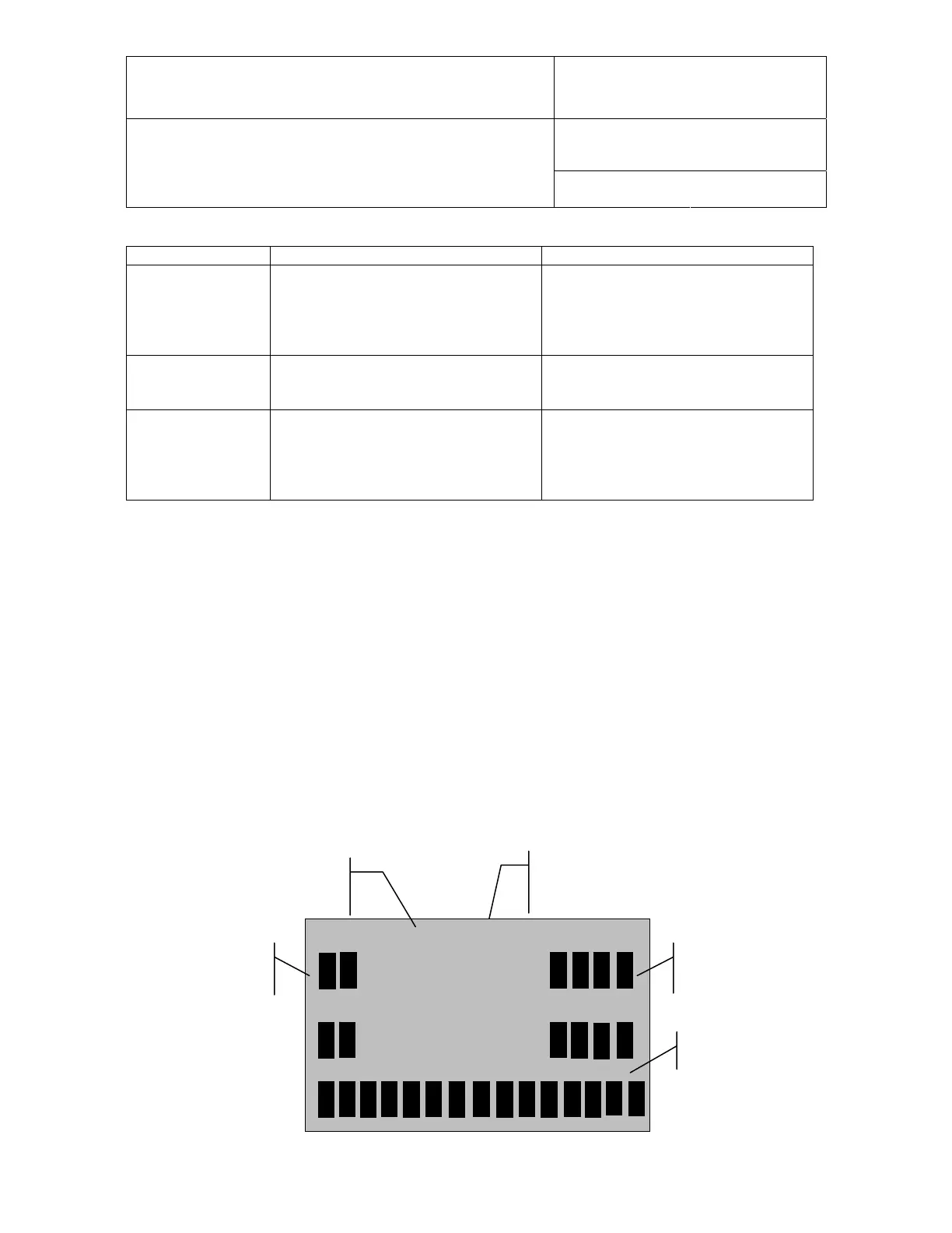
2.4 Optional display and keypad
The LC display shows which probe input is being displayed (small indicator on top of the display)
and up to 2 parameters measured by the probe, with the associated engineering unit. When
relevant, the message line provides additional information.
Humidity and Temperature
Calculated Value and Temperature
Calculated Value and Humidity
Engineering
Units
8.8:8.8
8.8:8.8
S S
Parameter or
Trend Indicators
Message Line
Probe Input Indicator
(1-2) from left to right