IN-E-HyFlex-V4_10
Rotronic AG
Bassersdorf, Switzerland
Document code Unit
Instruction Manual
Document Type
HygroFlex transmitter version 4: instruction
manual
Document title
Page 18 of 61
© 2006; Rotronic AG IN-E-HyFlex-V2_10.doc
5 Mechanical installation
Each HygroFlex transmitter is shipped in an individual box, separately from the probe. The shipping
box has a label with the following information: instrument type, main specifications and serial
number. An identical label is located inside of the transmitter enclosure.
5.1 Installation of the transmitter enclosure
Note: see appendix 8 for the optional metal enclosure
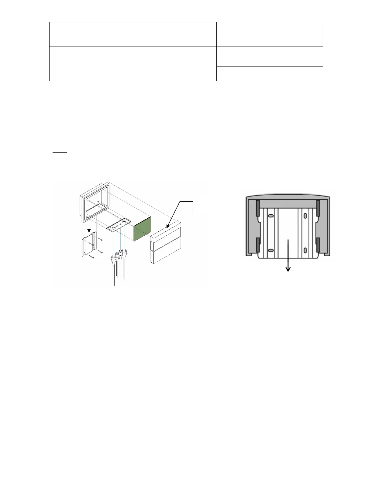
The HygroFlex is comprised of 5 parts: mounting bracket (1), electronics housing (2), main circuit
board (3), connector plate (4) and front cover with or without optional display and keypad (5).
V-shaped
slot
2
3
5
4
1
After unpacking the
HygroFlex, separate the
mounting bracket from the
back of the housing.
To attach the transmitter to a mounting surface:
1) Attach the wall plate in the position shown above to an appropriate surface using 4 screws.
2) Slide the electronics housing down on the wall plate to the mechanical stop