IN-E-HyFlex-V4_10
Rotronic AG
Bassersdorf, Switzerland
Document code Unit
Instruction Manual
Document Type
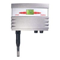
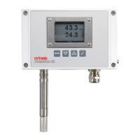
HygroFlex transmitter version 4: instruction
manual
Document title
Page 2 of 61
© 2006; Rotronic AG IN-E-HyFlex-V2_10.doc
Contents
1 Overview ................................................................................................................................4
2 General description ..............................................................................................................6
2.1 Power requirements............................................................................................................6
2.2 Probes and probe Inputs.....................................................................................................6
2.3 Analog outputs (HygroFlex 1 and 3) ...................................................................................8
2.4 Optional display and keypad...............................................................................................9
2.5 Serial interface (HygroFlex 2 and 3) .................................................................................10
2.6 Optional Ethernet (TCP/IP) interface (HygroFlex 2 and 3) ...............................................11
3 Optional configuration and communication software ....................................................12
4 How to configure the HygroFlex .......................................................................................12
4.1 Internal service connector (HygroFlex configuration) .......................................................13
4.2 Resolution of the analog signals (HygroFlex 3)................................................................13
4.3 Baud rate compatibility requirements ...............................................................................14
4.4 Ethernet local area network ..............................................................................................14
4.5 RS-485 multi-drop network (HygroFlex 2 and 3) ..............................................................15
4.6 Selection of the probe supply voltage (main PCB) ...........................................................16
4.7 Analog signal configuration (HygroFlex 1 and 3 main PCB) ............................................17
5 Mechanical installation.......................................................................................................18
5.1 Installation of the transmitter enclosure ............................................................................18
5.2 Front cover removal ..........................................................................................................19
5.3 Front cover installation......................................................................................................20
5.4 Re-attaching the ribbon cable (cover with optional display and keypad) .........................21
5.5 Probe installation guidelines .............................................................................................22
6 Electrical installation..........................................................................................................23
6.1 Main PCB connectors .......................................................................................................23
6.2 Optional Ethernet module (HygroFlex 2 and 3) ................................................................24
6.3 Mains fuse.........................................................................................................................24
6.4 PCB number......................................................................................................................25
6.5 Connector plate.................................................................................................................25
6.6 Connector plate connectors - pin-out diagrams................................................................27
6.7 Electrical diagrams (analog outputs) ................................................................................28
6.8 Cable grips........................................................................................................................30
6.9 Grommet for the Ethernet cable (HygroFlex 2 and 3 option)............................................30
6.10 Grounding .........................................................................................................................31
6.11 RS-485 multi-drop network (HygroFlex 2 and 3) ..............................................................31
7 HygroFlex function menu...................................................................................................32
7.1 CALCULATE (HygroFlex 2 and 3)....................................................................................33
7.2 DISPLAY ...........................................................................................................................34
7.3 ADJUST M.PT...................................................................................................................34
7.4 ADJUST 1PT.....................................................................................................................36
7.5 ADJUST REF....................................................................................................................37
7.6 PROBE..............................................................................................................................38
7.7 SETTINGS ........................................................................................................................38
7.8 SYS Status........................................................................................................................39
7.9 OUTPUT ...........................................................................................................................39
8 Error and status messages................................................................................................39
9 Test connector for the HygroPalm indicator....................................................................40
9.1 Display the Probe Measurements.....................................................................................41
9.2 Functions (except ADJUST M.PT and ADJUST 1PT)......................................................41