Capnograph and Ventilator
Revision C, August 2013
14-3
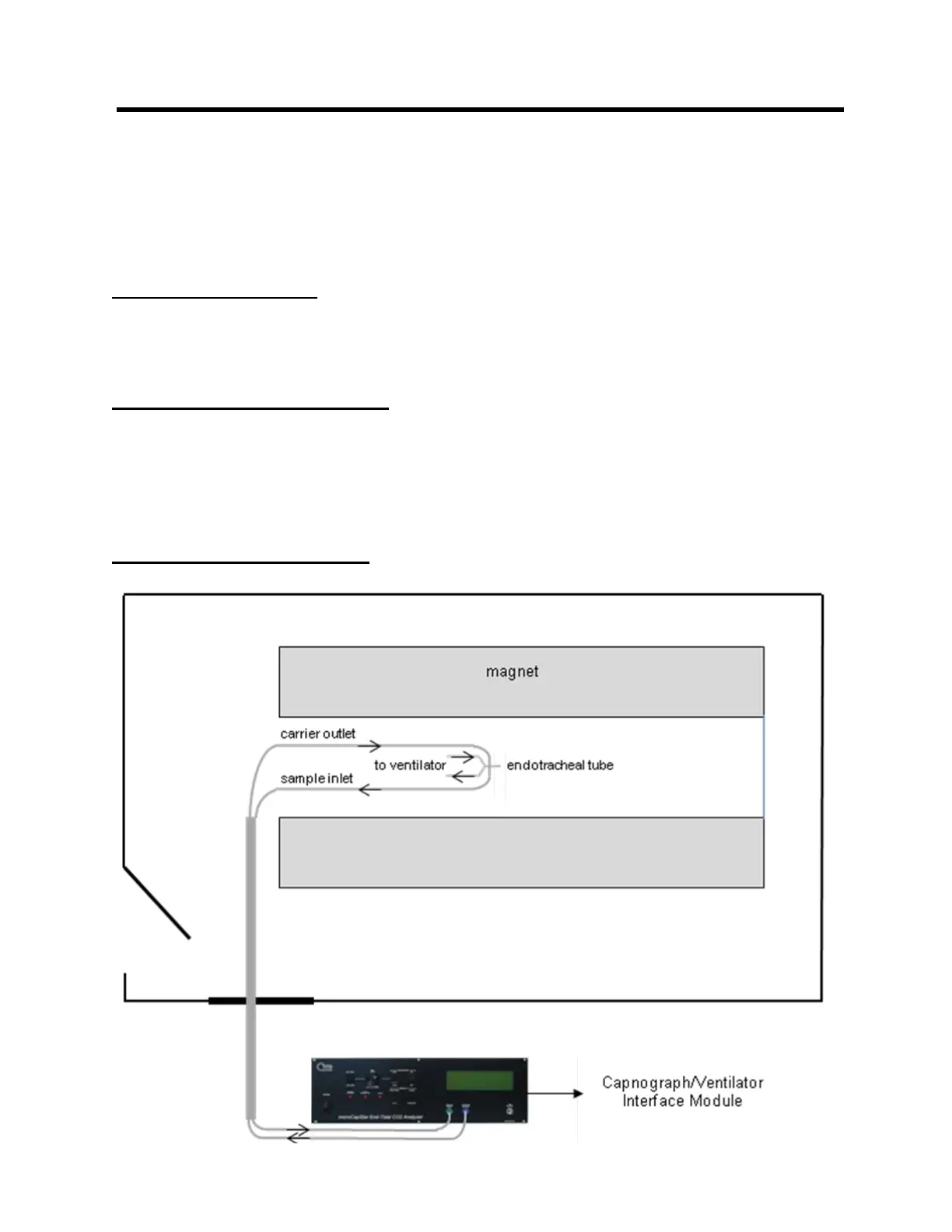
The diagram above shows connections between the Control Unit and the Valve
Assembly as well as connections to components of an anesthesia setup. The ventilator
should be located near a waveguide and accessible to the operator. Long cables are
provided to connect to the Capnograph/Ventilator Interface Module.
Ventilator operation
Refer to the MRI-1 Ventilator Instruction Manual for detailed instructions for connecting
and using the ventilator.
microCapStar Capnograph
A miniature, infrared CO2 sensor with a temperature controlled sample cell prevents
water condensation even during long measurement sessions. Low sample flow and
rapid response is achieved with a carrier gas system where the high flow carrier gas
quickly brings the low flow sample to the sample cell.
Capnograph setup in MR