Signal Breakout Module
Revision C, August 2013
16-2
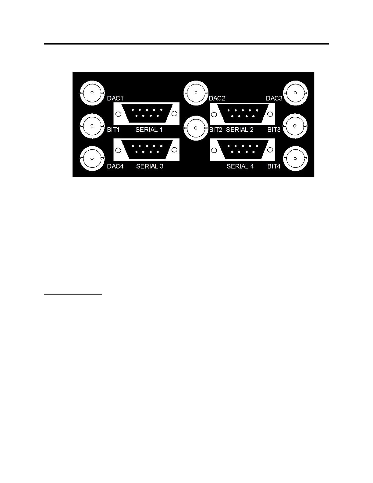
Physiological measurement output panel
Analog output 0 – 5 V channel 1
Gate output 0 – 5 V channel 1
Analog output 0 – 5 V channel 2
Gate output 0 – 5 V channel 2
Analog output 0 – 5 V channel 3
Gate output 0 – 5 V channel 3
Analog output 0 – 5 V channel 4
Gate output 0 – 5 V channel 4
Setup and use
The Signal Breakout Module connects, using 9-pin D serial cables, to the PC and to the
ERT Control/Gating Module. It gets power from the PC over the serial cable or from a
dedicated 12 VDC power supply. or from the ERT Control/Gating Module using a daisy
chain cable.
Clicking on the “BrkOut” key on the bottom of PC-sam’s main display opens the
BREAKOUT window, shown on the next page. The window has 4 independent
channels with drop down menus to set bit (gate), DAC (analog) and serial outputs for
each channel. The bit channels can be inverted. For the DAC and serial outputs a
selection between slow data or waveform data should be made before opening the drop
down menu.
Note the box at the bottom of the BREAKOUT window. This box must be checked to
enable PC-sam to send commands to the Signal Breakout Module.