English
8
41
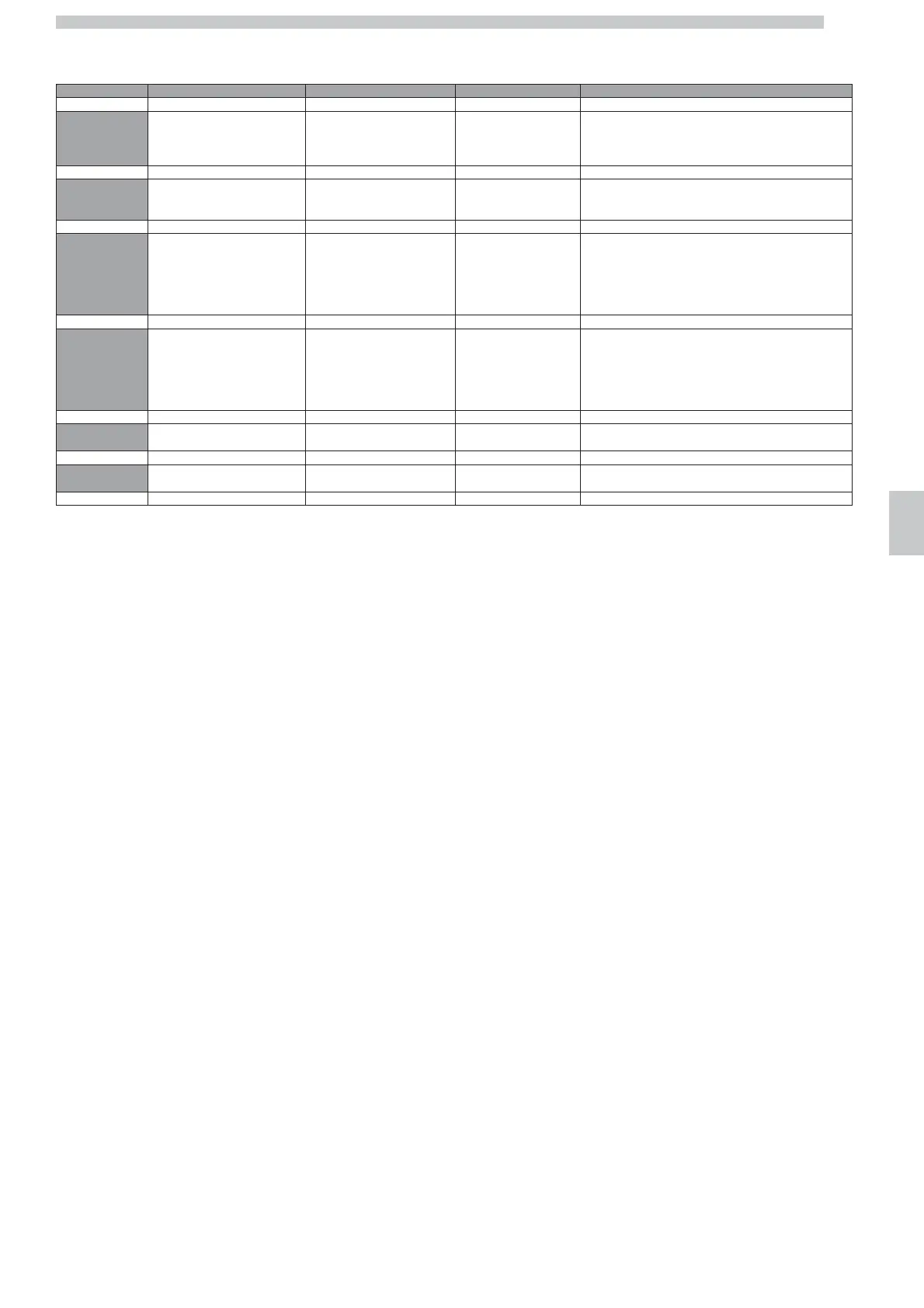
The testing procedures are summed up in the following table, where the tests for each menu page are shown after pressing the A, B, C and D
buttons.
Menu Page A button B button C button D button
M1
The gearmotor of the group is
turned on until it reaches the W
brewing position.
(*)
The gearmotor of the group is
turned on until it reaches the N
off position.
The Red LED light is
switched on in the
CPU/IO board
The coffee grinder motor is turned on and the number of
coffee grinder turns are displayed in the lower line on the
bottom right.
M2
The HOT WATER and STEAM
BOILER RE2 heating element is
powered
The HOT WATER and STEAM
BOILER RE1 heating element is
powered
The COFFEE BOILER RC
heating element is
powered
The CUP WARMING SURFACE PS heating element is
powered
M3 PC1+PC2+EVI PC1+PC2+EV1+EVC PC1+PC2+EV1+EVM PC1+PC2+EV1+EVM+EVC
Coffee pumps + Inlet solenoid
valve
Coffee pumps + Inlet solenoid
valve + Coffee solenoid valve
Coffee pumps + Inlet
solenoid valve + Mix
water solenoid valve
Coffee pumps + Inlet solenoid valve + Mix water solenoid
valve + Coffee solenoid valve
M4 PA3+PA4+EVI PA3+PA4+EVI+EVL PA3+PA4+EVI+EVA
Turns the coffee grinder counter-clockwise.
If the grinders are blocked, the coffee grinder can sometimes
be released.
(*)
Water pumps + Inlet solenoid
valve
Water pumps + Inlet solenoid
valve + Level solenoid valve
Water pumps + Inlet
solenoid valve + Water
solenoid valve
M5 EV10 EV8 EV8 Cold water solenoid valve + Inlet solenoid valve
Drain solenoid valve Clamp solenoid valve Steam solenoid valve
M6
Automatic steam wand solenoid valve Electromechanical pulse counters
Left and Right Led alternated (model DUO)
(*) :
As regards the DUO model, first select the grinder to be checked and then enter the Test Menu
 Loading...