Chapter 6: Programming Features
Firmware – S2011 and S3012
Revision: 1 (9/98) 40 © Saftronics, Inc.
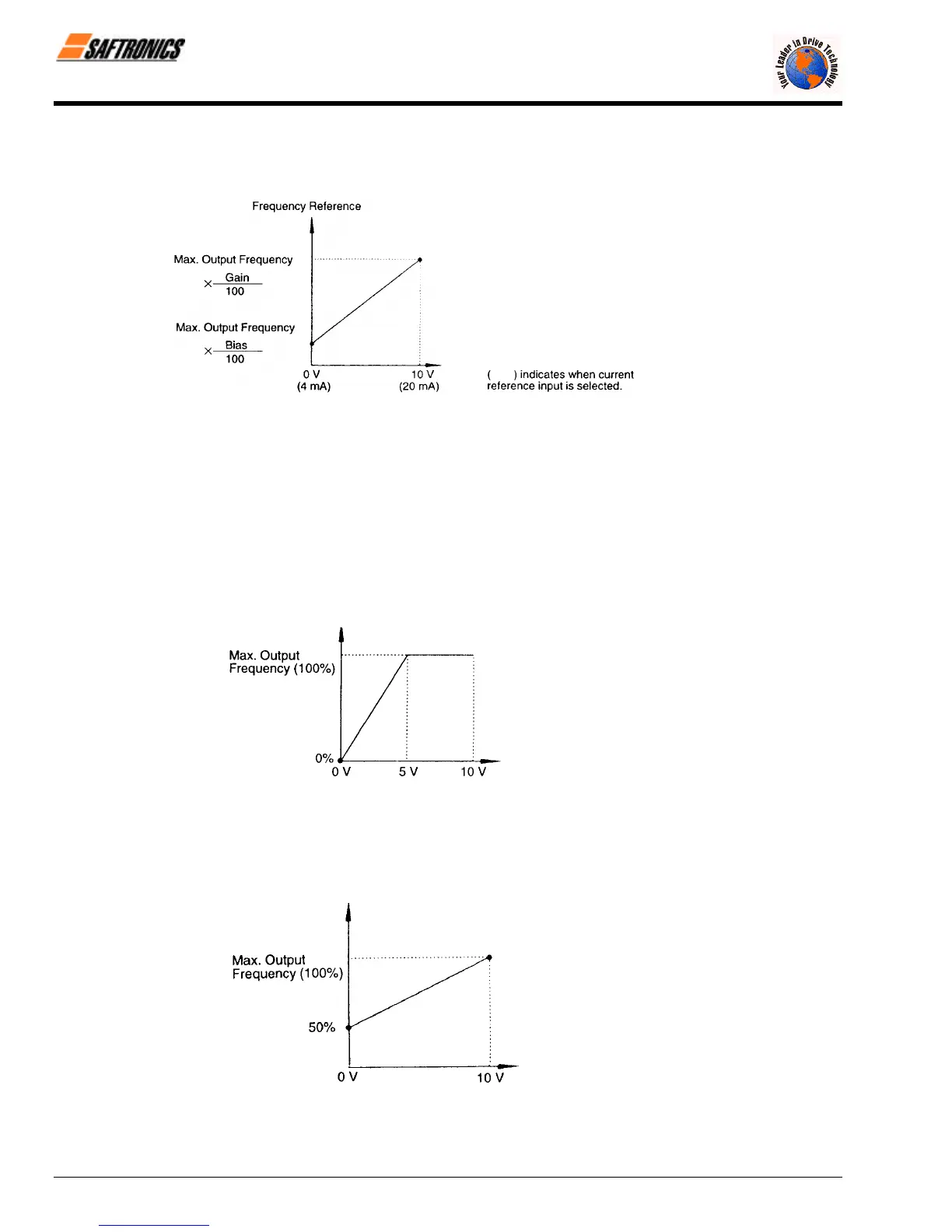
6.3.4. Adjusting Frequency Setting Signal
When the frequency reference is output by an analog input of control circuit Terminals FV and FI, the relationship between
the analog input (voltage/current) and the frequency reference can be set.
Figure 21 Frequency Signal Adjustment
§ Frequency Reference Gain (n046)
The frequency reference at the analog input value of 10V (20mA) can be set in units of 1%. (n012 Maximum output
frequency: 100%) Factory setting: 100%
§ Frequency Reference Bias (n047)
The frequency reference at the analog input value of 0 V (4 mA) can be set in units of 1%. (n012 Maximum output
frequency: 100%) Factory setting: 0%
Typical setting
• To operate the Inverter with frequency reference of 0% to 100% at 0 to 5V input.
Gain: Constant n046 = 200
Bias: Constant n047 = 0
Figure 22 Frequency Signal Adjustment Example
(0 to 5V Input)
• To operate the Inverter with frequency reference of 50% to 100% at 0 to 10V input.
Gain: Constant n046 = 100
Bias: Constant n047 = 50
Figure 23 Frequency Signal Adjustment Example
(0 to 10V Input)
efesotomasyon.com - Control Techniques,emerson,saftronics -ac drive-servo motor