Chapter 3: Wiring
Firmware – S2011 and S3012
Revision: 1 (9/98) 21 © Saftronics, Inc.
3.3 Wiring the Control Circuit
The following table outlines the functions of the control circuit terminals. Wire according to each terminal function.
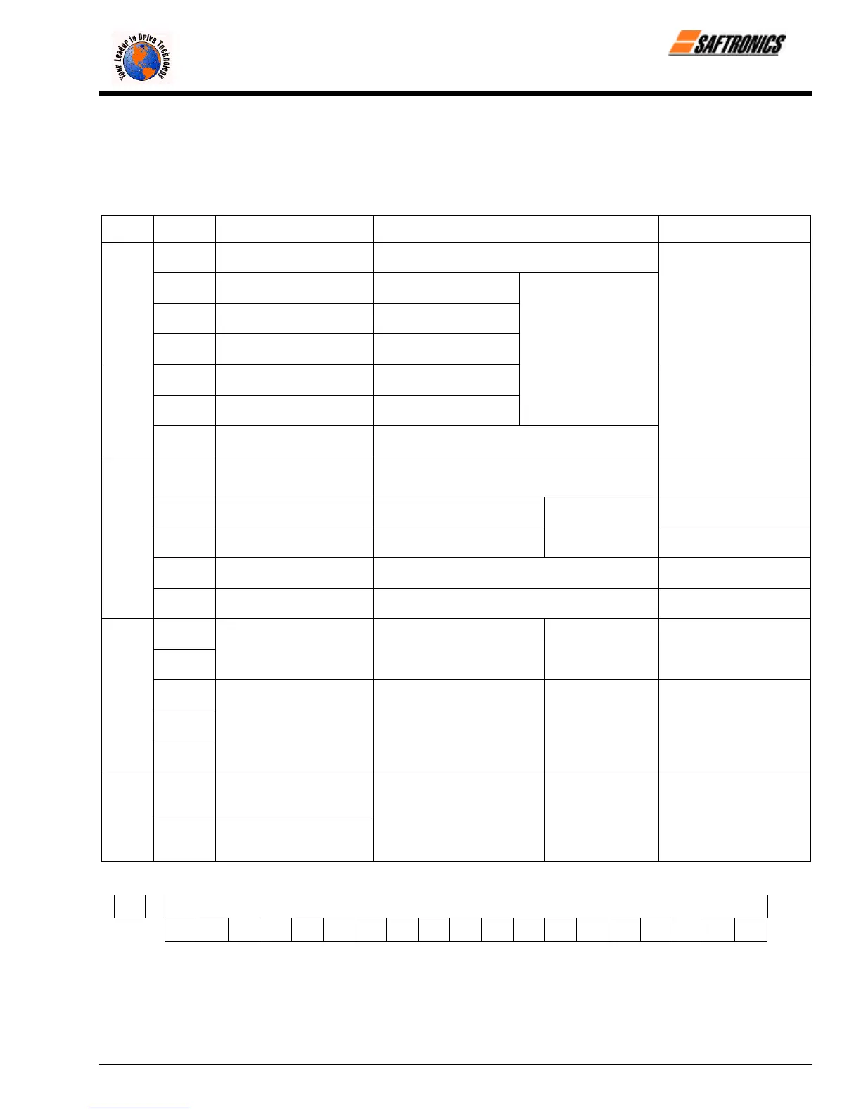
3.3.1 Functions of Control Circuit Terminals
Table 8 Control Circuit Terminals
Classi-
fication
Terminal Signal Function Description Signal Level
S1 Forward run/stop Forward run when closed, stop when open
S2 Reverse run/stop
Reverse run when closed,
stop when open
S3 External fault input
Fault when closed,
normal state when open
S4 Fault reset input Reset when closed
S5 Multi-step speed reference 1 Effective when closed
S6 Multi-step speed reference 2 Effective when closed
Multi-function contact
inputs (n035 to n039)
Sequence Input Signal
SC
Sequence control input
common terminal
Photo-coupler insulation
Input: + 24 VDC 8 mA
FS
+ 15 V
Power supply output
For analog command + 15 V power supply
+ 15 V
(Allowable current 20 mA
maximum)
FV
Frequency reference input
(voltage)
0 to + 10 V/100% 0 to + 10 V (20 kΩ)
FI
Frequency reference input
(current)
4 to 20 mA/100%
n042 = 0 : FV
effective
n042 = 1 : FI
effective
4 to 20mA (250Ω)
FC
Common terminal for control
circuit
0 V
Analog Input Signal
G
Connection to shield sheath
of signal lead
M1
M2
During running (NO contact) Closed when running
Multi-function
contact output
(n041)
Dry contact
Contact capacity:
250 VAC 1 A or less
30 VDC 1 A or less
MA
MB
Sequence Output Signal
MC
Fault contact output (NO/NC
contact)
Fault when closed between
Terminals MA and MC.
Fault when open between
Terminals MB and MC.
Multi-function
contact output
(n040)
Dry contact
Contact capacity:
250 VAC 1 A or less
30 VDC 1 A or less
AM Frequency meter output
Analog Output
Signal
AC Common
0 to + 10 V/100% frequency
Multi-function
analog monitor 1
(n048)
0 to + 10 V 2 mA or less
G
S1 S2 S3 SC SC S4 S5 S6 FV FI FS FC AM AC M1 M2 MA MB MC
Figure 11 Control Circuit Terminal Arrangement
efesotomasyon.com - Control Techniques,emerson,saftronics -ac drive-servo motor