Chapter 6: Programming Features
Firmware – S2011 and S3012
Revision: 1 (9/98) 60 © Saftronics, Inc.
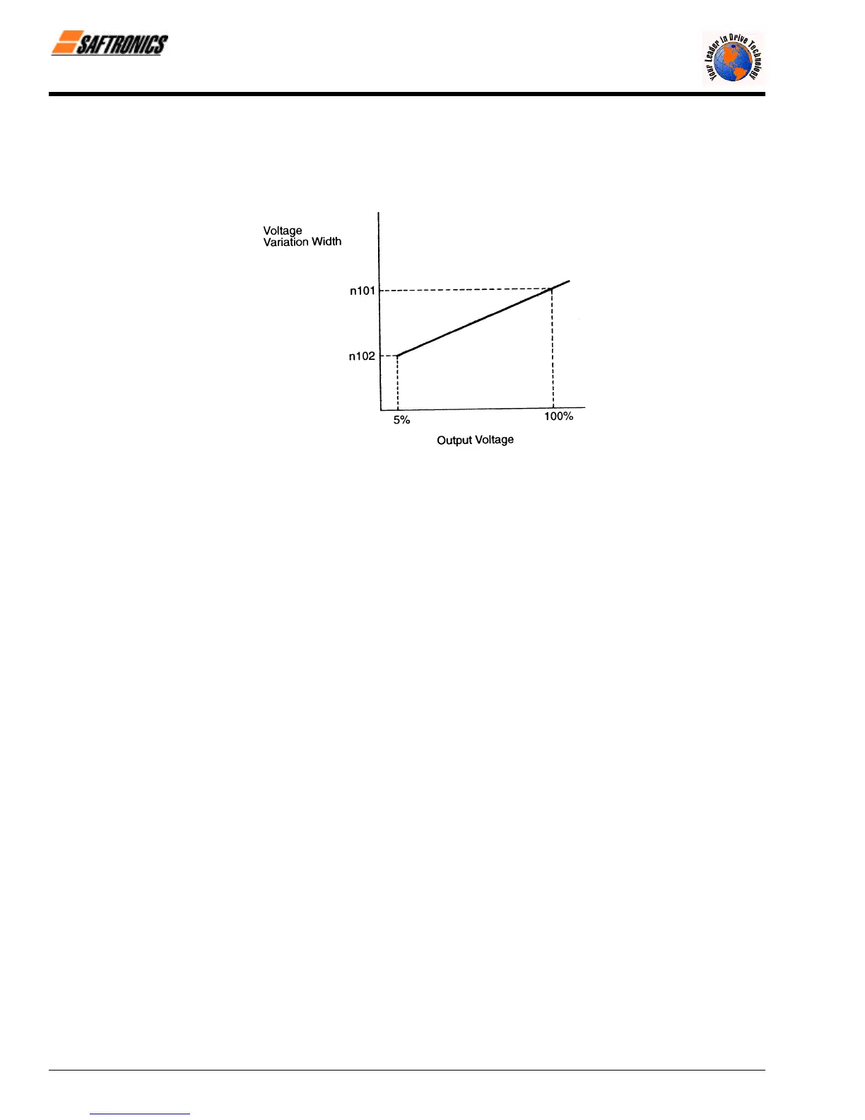
§ Step Voltage of Tuning (n100, n101)
Sets voltage variation width of one tuning cycle. Setting is made in a percentage of motor rated voltage. By
increasing this value, the rotating speed variation becomes larger. This voltage variation width is set when starting
tuning voltage is 100% and motor rated voltage is 5%. Values obtained by linear interpolation are set to any voltage
values other than these values.
Figure 51 Energy Saving Voltage Variation Width
6.10 MEMOBUS Control
FP5/GP5 can perform serial transmission by using a Programmable Controller (PLC) and MEMOBUS communication. MEMOBUS
is composed of one master PLC and 1 to 31 (maximum) slave units (FP5/GP5). In signal transmission (serial transmission)
between the master and slaves, the master always starts transmission and the slaves respond to it.
The master performs signal transmission with one slave at a time. Therefore, address numbers are assigned to each slave in
advance and the master specifies a number to perform signal transmission. The slave which receives the command from the
master executes the function and returns the response to the master.
6.10.1. Communication Specifications
• Interface
: RS-485 (Communication interface card SI-K2/P must be mounted.)
• Synchronization
: Asynchronous
• Transmission parameter
:
• Baud rate
: Selectable from 2400, 4800, 9600 BPS (Constant n107)
• Data length
: Fixed to 8 bits
• Parity
: Parity / no-parity, even / odd selectable (Constant n108)
• Stop bit
: Fixed to 1 bit
• Protocol
: In accordance with MEMOBUS
• Maximum number of units
to be connected
: 31 units (when RS-485 is used)
6.10.2. Data to be Sent/Received by Communication
Data to be sent/received by communication are RUN commands, frequency reference, fault contents, Inverter status and
constant setting/reading.
§ Operation Mode Selection (n002)
Select the RUN command and frequency reference input method in constant n002. To provide a RUN command
and frequency reference by communication, set this constant to settings 4 to 8. Also, without regard to this selection,
monitoring of running status, constant setting/reading, fault reset and multi-function input command from the PLC are
enabled. The multi-function input command becomes OR with the command input from control circuit Terminals S2
to S6.
efesotomasyon.com - Control Techniques,emerson,saftronics -ac drive-servo motor