Chapter 2: Installation
Firmware – S2011 and S3012
Revision: 1 (9/98) 8 © Saftronics, Inc.
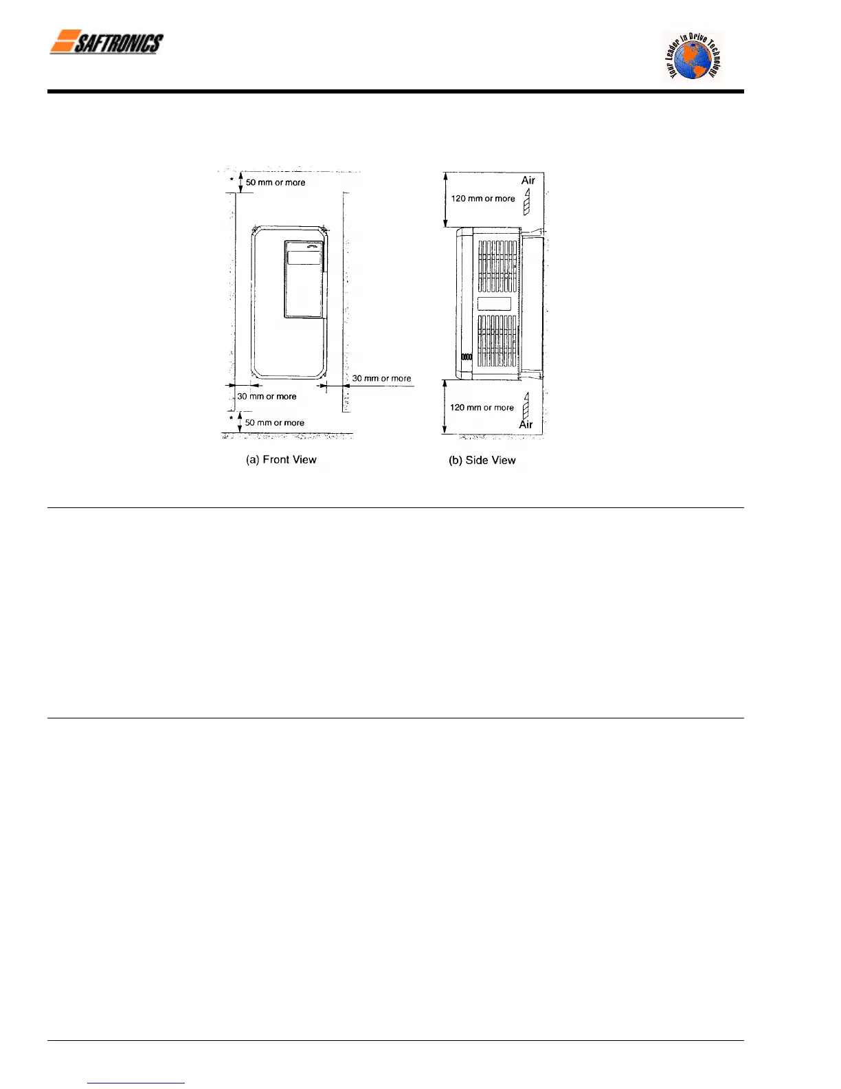
2.4 Clearances
Install the FP5/GP5 vertically and allow sufficient clearances for effective cooling as shown below.
Figure 8 Clearances
NOTE: 1. The clearances required at the top and bottom and both sides are common in open chassis type (IP00) and enclosed
wall-mounted type (NEMA1/IP20).
2. Remove the top and bottom covers to use the open chassis type of 200V/400V 15kW or less.
3. When installing the models of 200V/400V 30kW or more equipped with eyebolts, extra spacing will be required on either
side. For detailed dimensions, contact your Saftronics representative.
4. For the external dimensions and mounting dimensions, refer to Chapter 10 Dimensions.
5. Allowable intake air temperature to the Inverter:
• Open chassis type (IP00) : - 10°C to 45°C
• Enclosed wall-mounted type : - 10°C to 40°C (NEMA 1/IP20)
6. Ensure sufficient space for the sections at the upper and lower parts marked with [ in order to permit the flow of
intake/exhaust air to/from the Inverter.
efesotomasyon.com - Control Techniques,emerson,saftronics -ac drive-servo motor