Chapter 3: Wiring
Firmware – S2011 and S3012
Revision: 1 (9/98) 10 © Saftronics, Inc.
WARNING
Only commence wiring after verifying that the power supply is turned OFF. Failure to observe this can result in an electrical shock or
fire.
• Wiring should be performed only by qualified personnel. Failure to observe this can result in an electrical shock or fire.
When wiring the emergency stop circuit, check the wiring thoroughly before operation. Failure to observe this can result in personal
injury.
CAUTION
• Verify that the Inverter rated voltage coincides with the AC power supply voltage. Failure to observe this can result in personal injury
or fire.
• Do not perform a withstand voltage test of the Inverter. It may cause semi-conductor elements to be damaged.
To connect a Braking Resistor, Braking Resistor Unit or Braking Unit, follow the procedures described in Chapter 11. Improper
connection may cause fire.
• Tighten terminal screws to the specified tightening torque. Failure to observe this can result in a fire.
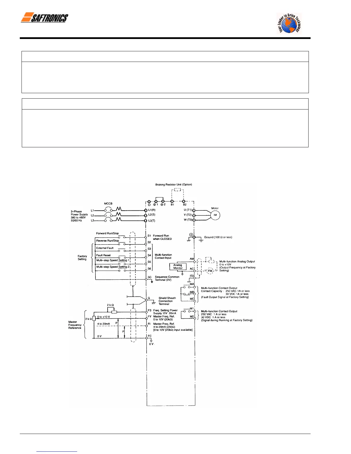
3.1 Connection Diagram
Below is a connection diagram of the main circuit and control circuit. Using the Digital Operator, the motor can be operated by
wiring the main circuit only.
Figure 9 FP5/GP5 Connection Diagram
efesotomasyon.com - Control Techniques,emerson,saftronics -ac drive-servo motor