Chapter 3: Wiring
Firmware – S2011 and S3012
Revision: 1 (9/98) 13 © Saftronics, Inc.
• Use the ground wires described in Tables 5 or 6 and keep the length as short as possible.
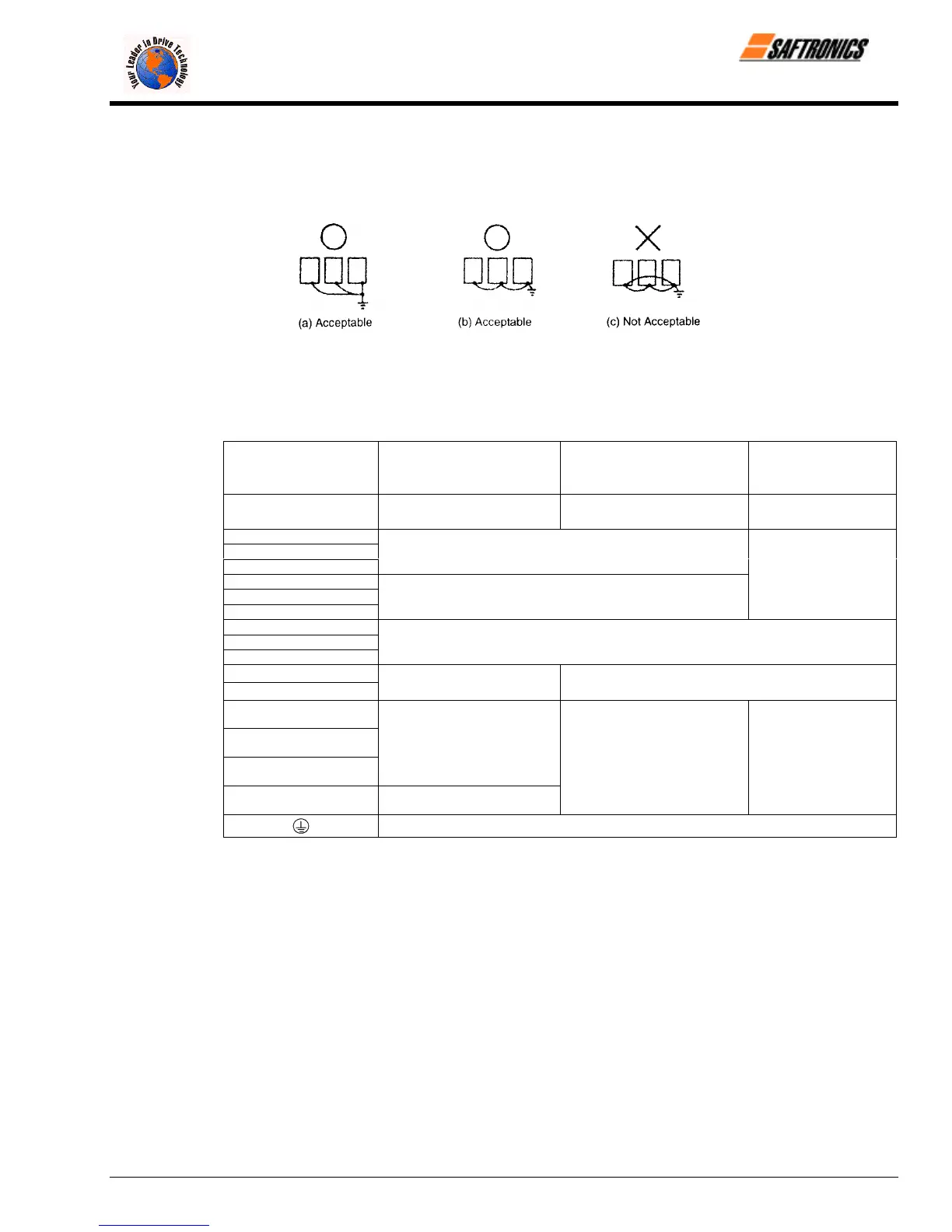
• When using several Inverter units side by side, ground the units as shown in Figure 10, (a) or (b). Do not loop the
ground wires as shown in (c).
Figure 10 Grounding of Three Inverter Units
3.2.4 Functions of Main Circuit Terminals
The following table outlines the functions of the main circuit terminals. Wire according to each terminal function.
Table 3 200 V Class Terminal Functions
Models
FP5/GP5
23P7 to 27P5 2011 to 2015 2018 to 2075
Max Applicable Motor
Output
3.7 to 7.5 kW 11 to 15 kW 18.5 to 75 kW
L1 (R)
L2 (S)
L3 (T)
Main circuit input power supply
L11 (R1)
L21 (S1)
L31 (T1)
Main circuit input
power supply
T1 (U)
T2 (V)
T3 (W)
Inverter output
B1
B2
Braking Resistor Unit
Ö
¾ 1
¾ 2
• DC Reactor (¾1 − ¾2)
• DC bus terminals (¾1 − ¾2
¾ 3
• DC Reactor (¾1 − ¾2)
• DC bus terminals (¾1 − ¾2
• Braking Unit (¾3 − Ö)
Ground terminal (Ground resistance: 100 Ω or less)
efesotomasyon.com - Control Techniques,emerson,saftronics -ac drive-servo motor