Chapter 3: Wiring
Firmware – S2011 and S3012
Revision: 1 (9/98) 14 © Saftronics, Inc.
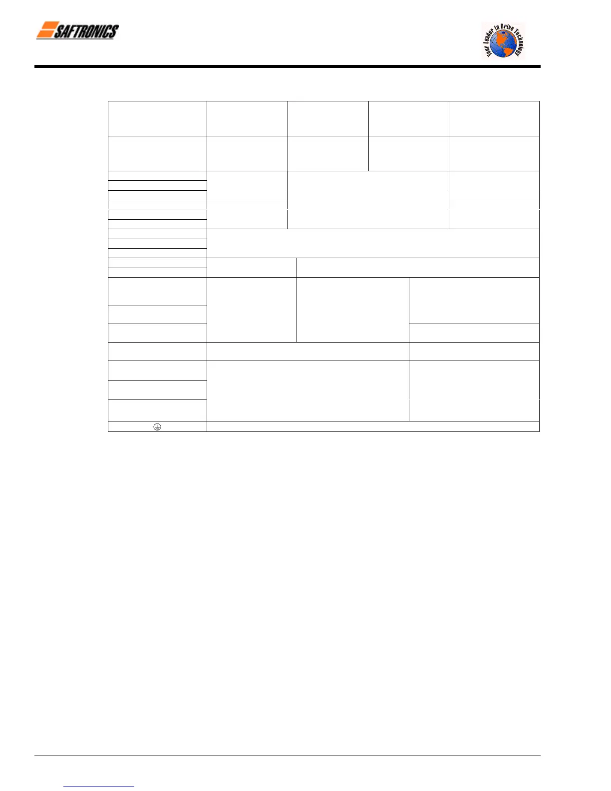
Table 4 400 V Class Terminal Functions
Models
FP5/GP5
40P4 to 4015 4018 to 4045 4055 to 4160 4185 to 4300
Max Applicable Motor
Output
0.4 to 15 kW 18.5 to 45 kW 55 to 160 kW 185 to 300 kW
L1 (R)
L2 (S)
L3 (T)
Main circuit input
power supply
Main circuit input
power supply
L11 (R1)
L21 (S1)
L31 (T1)
Main circuit input power supply
T1 (U)
T2 (V)
T3 (W)
Inverter output
B1
B2
Braking Resistor Unit
Ö
¾ 1
• Braking Unit (¾ 3 − Ö)
¾ 2
• DC Reactor
(¾1 − ¾2
• DC bus terminals
(¾1 − Ö)
¾ 3
• Braking Unit (¾ 3 − Ö)
r (l 1)
s 200 (l 2 200)
s 400 (l 2 400)
Cooling fan power supply
(Control power supply
r (l 1) − s 200 (l 2 200):
200 to 230 VAC input
r (l 1) − s 400 (l 2 400):
380 to 460 VAC input
Ground terminal (Ground resistance: 10Ω or less)
efesotomasyon.com - Control Techniques,emerson,saftronics -ac drive-servo motor