Chapter 3: Wiring
Firmware – S2011 and S3012
Revision: 1 (9/98) 20 © Saftronics, Inc.
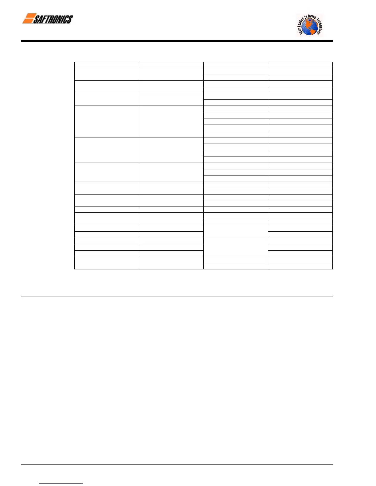
Table 7 Closed-Loop Connectors
AWG Size Wire Size mm
2
Terminal Screw Closed-Loop Connectors
M3.5
1.25 − 3.5
20 0.5
M4
1.25 − 4
M3.5
1.25 − 3.5
18 0.75
M4
1.25 − 4
M3.5
1.25 − 3.5
16 1.25
M4
1.25 − 4
M3.5
2 − 3.5
M4
2 − 4
M5
2 − 5
M6
2 − 6
14 2
M8
2 − 8
M4
5.5 − 4
M5
5.5 − 5
M6
5.5 − 6
12-10 3.5 / 5.5
M8
5.5 − 8
M5
8 − 5
M6
8 − 6
8 8
M8
8 − 8
M6
14 − 6
6 14
M8
14 − 8
M6 14 - 6
4 22
M8 14 - 8
3-2 30 / 38 M8
38 − 8
M8
60 − 8
1-1/0 50 / 60
M10
60 − 10
3/0 80
80 − 10
4/0 100
M10
100 − 10
4/0 100
100 − 12
300MCM 150
150 − 12
400MCM 200
M12
200 − 12
M12 x 2
325 − 12
650MCM 325
M16
325 − 16
NOTE: When determining wire size, consider voltage drop. Select a wire size so that voltage drop will be less than 2% of the normal
rated voltage. Voltage drop is calculated by the following equation:
Phase-to-phase voltage drop (V) = /3 5 wire resistance (Ω/km) 5 wiring distance (m) 5 current (A) 5 10
−3
efesotomasyon.com - Control Techniques,emerson,saftronics -ac drive-servo motor