INTRODUCTION
1.4 Revised 10/02/2012
Unloading Indicator
..4.
. — provides an indication of the
status of the Unloading Station access door:
Light Off – indicates “access denied” to the Unloading
Station access door; the door should not be opened. The
Unloading Indicator is “off” whenever the Unloading
Station is empty or when the Transferring Arm is in
motion.
Light On – indicates “access permitted” to the Unloading
Station access door; the door can be opened. The
Unloading Indicator is “on” when there is a basket in the
Unloading Station and the Transferring Arm is stationary.
Flashing – alerts the operator to remove the basket(s)
from the unloading station or the access door is open
and needs to be closed immediately.
Audible Alarm (not shown) – indicates the following:
• A tone sounds at the completion of a processing cycle
(when a basket has arrived at the Unloading Station).
Tone selection (from seven available tones), volume
selection (high, middle, low), and pattern selection
(continuous, intermittent, 30 seconds only) are user
selectable (see “Configuring System Settings” on page
3.2 for details).
• A continuous tone sounds if an abnormal condition is
detected during processing. The alarm condition must
be acknowledged and/or cleared by the operator to
cancel the alarm. Tone selection (from seven availa-
ble tones) and volume selection (high, mid, low) are
user selectable (see “Configuring System Settings” on
page 3.2 for details).
Retort Access Door
..5
.. — provides access to the
Microwave and Vacuum Stations for purposes of cleaning
and/or maintenance. Access to all four retorts is permit-
ted/denied, under software control, when the instrument is
processing specimens.
Retort #1 / #2 Reagent Cabinet Access Door
..6
.. —
provides access to retort #1 / #2 Reagent Cabinet for the
purposes of replacing reagents.
Retort #3 / #4 Reagent Cabinet Access Door
..7
.. —
provides access to the paraffin oven for the purposes of
replacing reagents.
Control Panel
..8
.. — comprises the controls and
indicators necessary to program and operate the instru-
ment, and to monitor the instrument during processing
(refer to “Control Panel (Figure 1-O)” on page 1.12 for
details).
Fume Control System Access Door
..9
.. — provides
access to the fume control system for purposes of
replacing the fume filter.
Overflow Bottle Access Door
..10
.. — provides access
to retorts #3 / #4 overflow bottles for purposes of cleaning
and servicing.
Leveling Feet/Casters
..11
.. — four casters are provided
to allow for easy repositioning of the instrument. Adjusta-
ble leveling feet associated with each caster facilitate
proper leveling of the instrument.
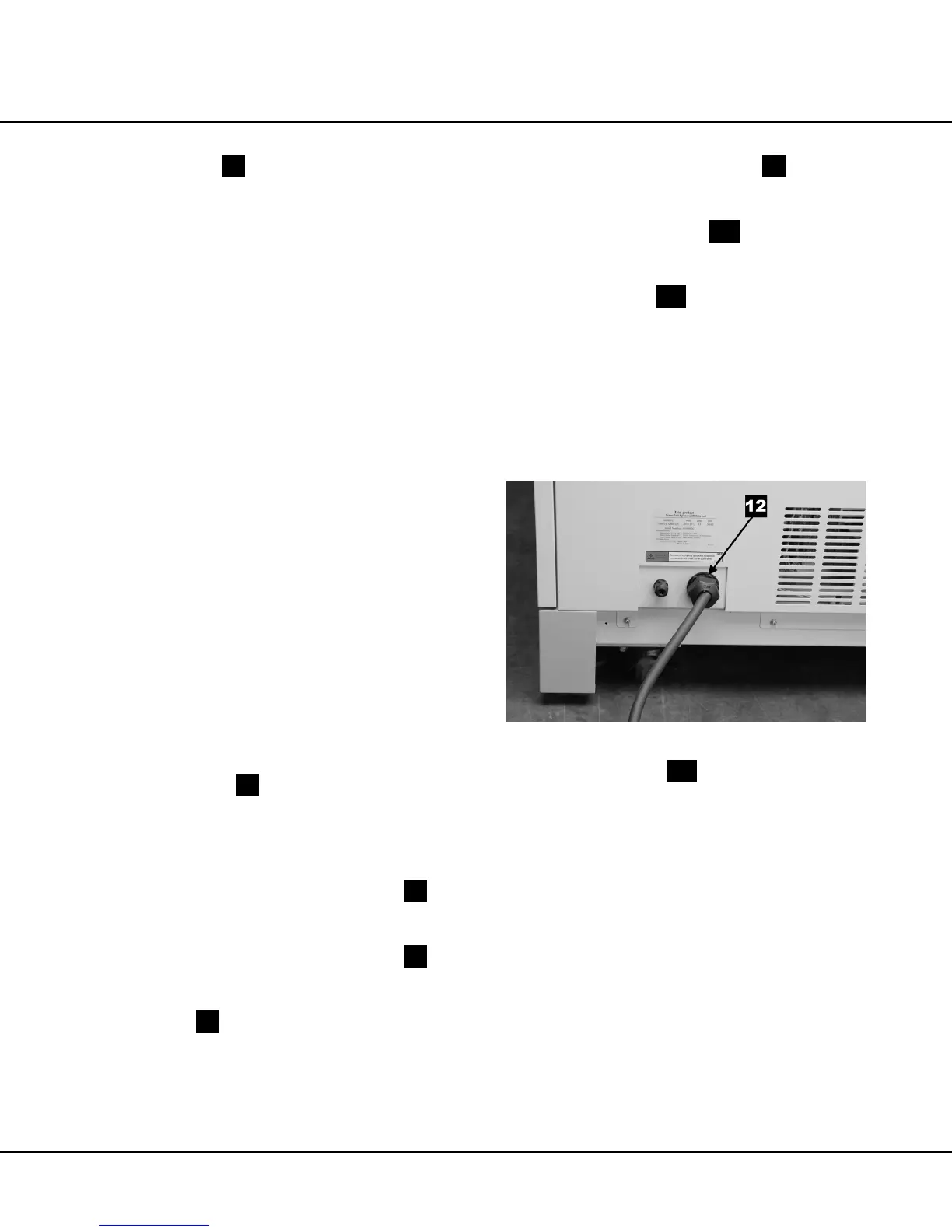
Cabinet Rear (Figure 1-B)
The power cord connector and external interface are
located at the rear of the back cabinet.
Figure 1-B
Power Cord Connector
..12
.. — accepts the instrument
end of the power cord; opposite end of the power cord
may be connected to facility power.
 Loading...