Index revision : C - November 2017 22 7030
3.3. Operating principle
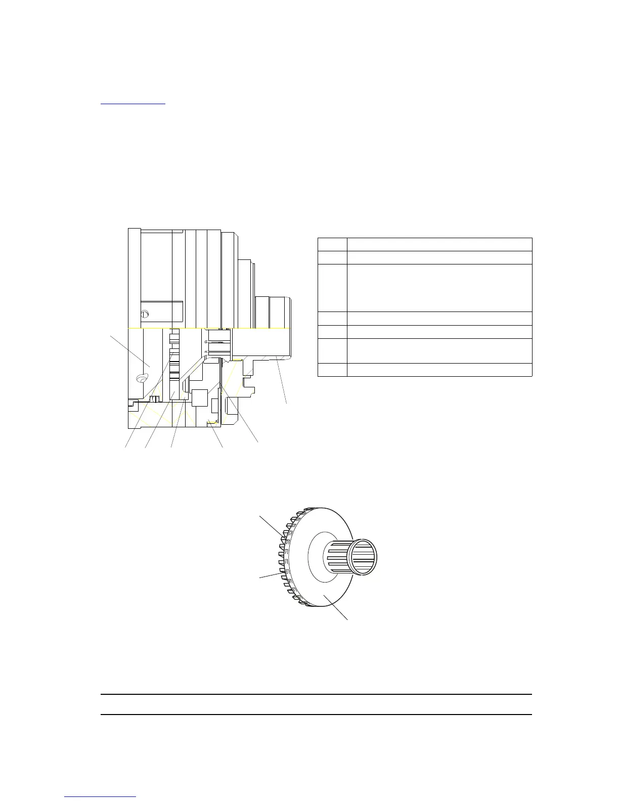
3.3.1. Turbine
see RT Nr 6350
This turbine has no mechanical shaft and is kept aligned simply by the polarity difference
between the bearing magnets. This system also completely eliminates friction.
The bearing air, which is uniformly distributed across the stator surface generates an air cushion,
separating rotor and stator. The rotor can turn freely, held in place by the balance of the
pressure and magnetic forces. The air directed onto the turbine blades makes it possible to
rotate or brake the rotor.
The product is sprayed due to the centrifugal forces generated by the bell cup rotation. To a
certain extent, the size of the particles sprayed decreases as the rotation speed increases.
1 Rotor
2 Stator magnet
3
Turbine body (stator) with a supply of:
- Bearing air
- Turbine rotation and braking air
- Shaping air
4 Openings for turbine braking
5 Teeth for turbine rotation
6
Drive vane for braking and
rotation
7 Deflector fitted with seal