Index revision : C - November 2017 34 7030
6.5. Injector holder
The injector holder is secured to the body of the PPH 308 by three M3 x 10 screws.
Its positioning pin ensures correct positioning.
6.6. Injector
6.6.1. Disassembly
• Switch off the machine.
• Remove bell cup (see RT Nr 6285).
• Remove outer cover.
• Remove shaping air shroud.
• Use a 2.5 mm Allen key to remove the five screws securing the turbine. Remove turbine.
• Use a 2.5 mm Allen key to remove the three screws securing the injector holder.
• Unscrew the injector (clockwise) using a 5 mm open-ended spanner, and remove it
carefully, to avoid damaging the injector and its two o-rings.
• Clean (see § 7 page 39).
6.6.2. Reassembly
• Clean (see § 7.2.3 page 42) the components and check their condition. Replace if
necessary.
• Insert the microphone seals into the manifold block.
• Put in place the injector holder with the aligment pin and tighten the three screws using a
2.5 mm Allen key.
• Fit both seals on the injector.
• Place the injector on the injector holder and tighten anticlockwise (figure 4) to a torque
of 3.5 Nm.
• Secure the turbine onto the elbow using the five screws and tighten to a torque of 1.5 Nm.
• Refit the shaping air shroud.
• Clip the bell cup onto the turbine.
• Put the outer cover in place, manually tighten then complete the tightening using the
special tool (P/N 1308689).
• Reconnect the power supply.
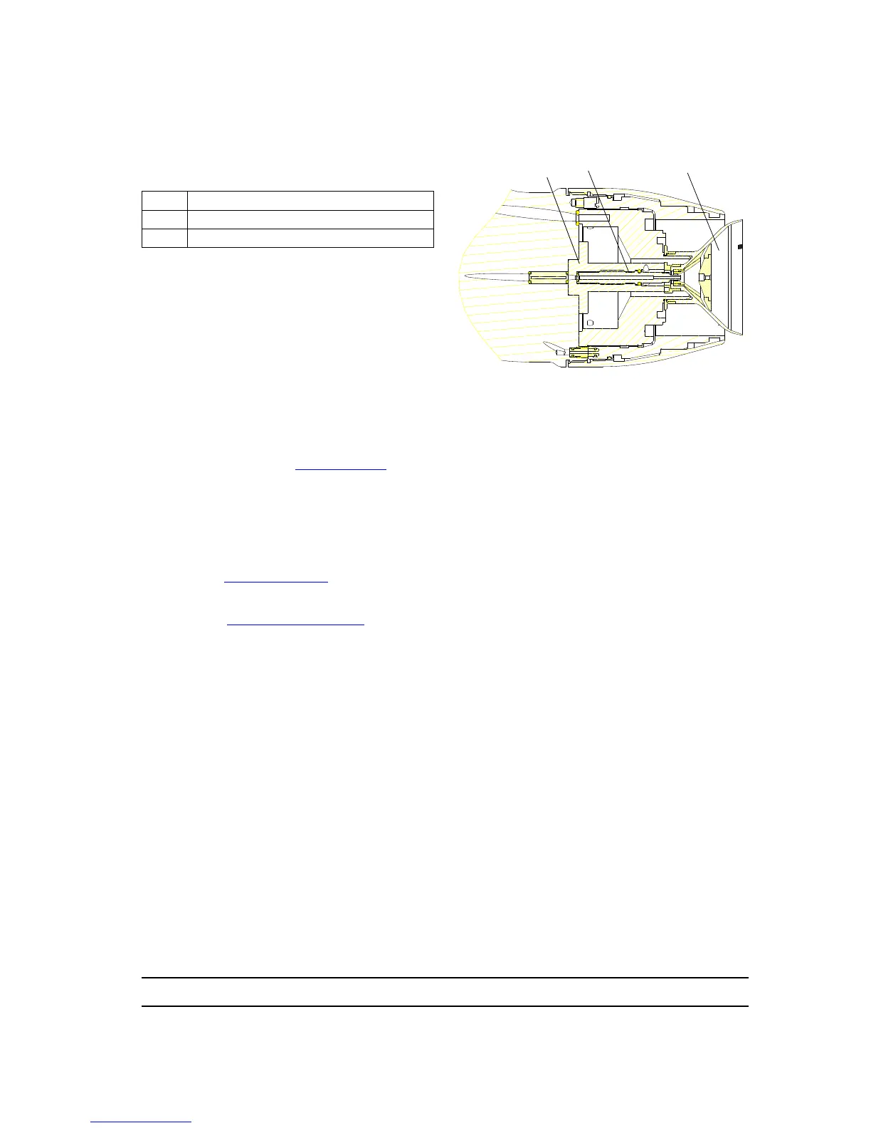
1 Injector holder
2 Injector
3 Bell cup