Index revision : C - November 2017 24 7030
4. Fluid Diagram of the Various Circuits
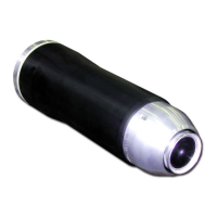
4.1. Paint flow diagram
For use of the rinsing circuit (generally used to change colours)
The “11” and ”41” hoses (5/8 PTFE) should be
sheathed with 9/12 PTFE hoses.
Note: PTFE hoses must never be replaced by polyamide hoses.
Blue hoses are used for the various different types of air supply.
Clear hoses are used for product.
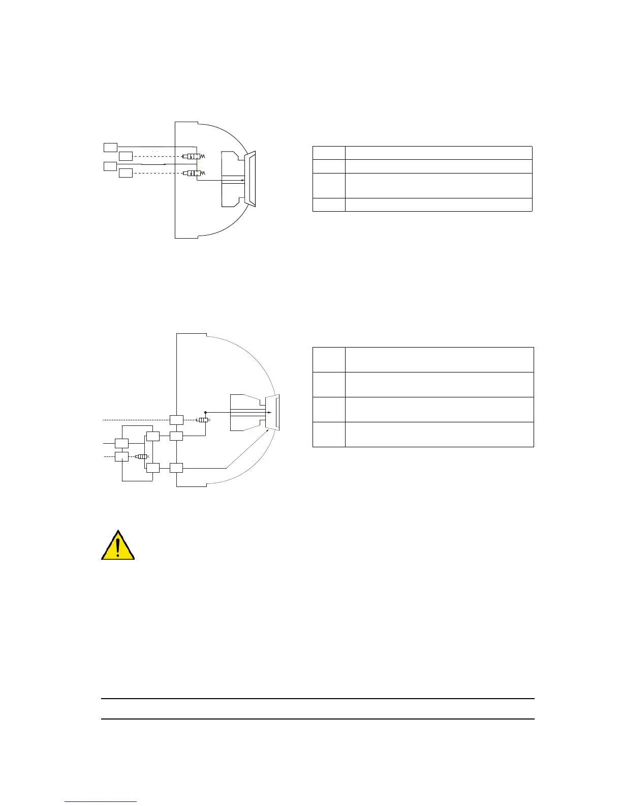
4.2. Bell cup and injector rinsing diagram
31: Bell cup rinsing - the bell cup is rinsed via the
air/solvent inlet.
32: The air/solvent supply rinses the paint supply
line up to the bell cup.
The “36” hose (4/6 PTFE) should be sheathed with 7/10 PTFE hose.
WARNING : The rinsing cycle must end with a compressed air sequence, circuits 31,32 and 36
must be purged and dried during 1 to 2 seconds before restarting the high voltage.
11 Paint supply - Dia. 5 x 8 PTFE
41 Dump - Dia 5 x 8 PTFE
51
Paint supply pilot -
Dia 2.7 x 4 - Polyamide
53 Dump pilot - Dia 2.7 x 4 - Polyamide
31
Solvent / air rinsing - Outside of bell
cup - Dia. 2 x 4 PTFE
32
Solvent / air rinsing - Injector - Dia. 2 x 4
PTFE
56
Solvent / air rinsing pilot - Injector - Dia.
2.7 x 4 - Polyamide
58
Solvent / air rinsing pilot - Outside of
bell cup - Dia. 2.7 x 4 - Polyamide