Index revision : C - November 2017 25 7030
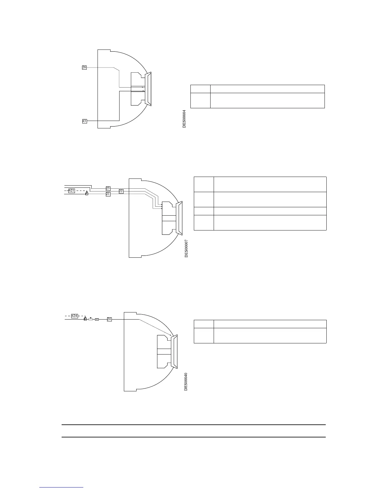
4.3. Microphone air diagram
The microphone air is controlled by a remote
regulator.
4.4. Turbine rotation diagram
23: The bearing air separates the rotor from the
stator.
22: Supplies turbine braking air.
21: Supplies turbine rotation air.
The bell cup speed control module activates
circuit 21 via a proportional air valve and circuit
22 via a solenoid valve.
4.5. Shaping air diagram
24 : The shaping air supply controls the pattern
diameter.
Shaping air is controlled via a proportional air
valve.
26 Microphone air - Dia. 4 x 6 - Polyamide
43
Microphone return supply - Dia. 4 x 6 -
Polyamide
21 Turbine rotation - Dia. 7 x 10 - Polyure-
thane
22 Turbine braking - Dia. 6 x 8 - Polyam-
ide
23 Bearing air - Dia. 4 x 6 - Polyamide
621
Turbine rotation control/regulation -
Dia 2.7 x 4 - Polyamide
24 Shaping air - Dia. 6 x 8 - Polyamide
624
Shaping air control/regulation - Dia.
2.7 x 4 - Polyamide