5.3 VALVE PLATE AND BI-METALLIC DISC
DISASSEMBLY/REPLACEMENT
First of all boost pump has to be disassembled: follow
instructions of chapter 5.2.
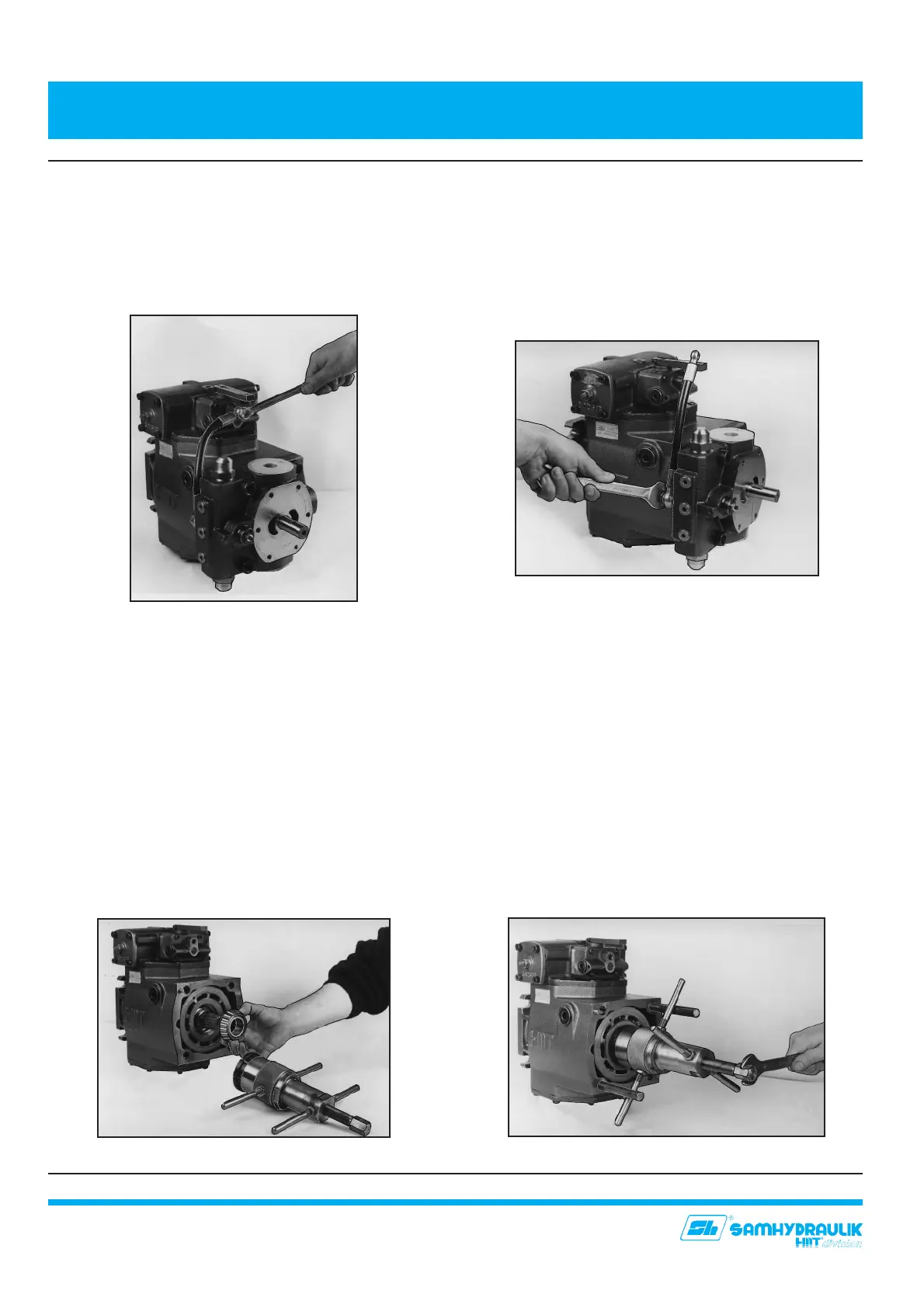
5.3.1 - Disassemble control feeding hose (78) fittings (77),
(100) and washers (76), (99) of the servo control
(fig. 6,7).
5.3.2 - Unscrew and remove screws (83) and (84), then
remove cover (2) taking care that the valve plate
(27) does not fall and and get damaged.
5.3.3 - Remove from cover (2) valve plate (27). Take away
seal (31).
5.3.4 - Remove pins (65). When they will be mounted
again, remember to put grease on them.
5.3.5 - Carefully clean surfaces with a wiping rag that do
not frays, so to clean them from dirt and
contaminations.
5.3.6 -In order to substitute bimetallic plate (96),
remove coupling (28) inside of which there is
a circlip (49), and rear tapered bearing (51),
using appropriate puller (fig.8,9), which you
can order.
5.3 SMONTAGGIO/SOSTITUZIONE DISCHI
DISTRIBUTORE E BIMETALLICO
Va innanzitutto smontata la pompa di sovralimentazione:
vedere le istruzione alla sezione 5.2.
5.3.1 - Smontare il tubo di alimentazione (78) il bullone e
il raccordo (77), (100) e le rondelle (76), (99) del
regolatore (fig. 6,7).
5.3.2 - Allentare ed estrarre le viti di fissaggio (83) ed (84)
e rimuovere il coperchio (2), facendo attenzione a
che il disco distributore (27) non cada e non si
danneggi.
5.3.3 - Staccare dal coperchio (2) il disco distributore (27).
Rimuovere la guarnizione (32)
.
5.3.4 - Rimuovere le spine (65). Nel rimontarle, ricordare
di mettere del grasso.
5.3.5 - Pulire con cura le superfici, con un panno pulito
non sfilacciabile, liberandole dalla presenza di
eventuali residui.
5.3.6 - Per potere sostituire il disco bimetallico (96),
occorre sfilare il giunto (28), all’interno del quale vi
è un anello elastico (49), e il cuscinetto a rulli conici
(51), utilizzando l’apposito estrattore (fig.8,9), che
potete ordinare.
5. SMONTAGGIO E RIMONTAGGIO DELLA POMPA
5. PUMP DISASSEMBLY AND ASSEMBLY
14
Fig. 6
Fig. 7
Fig. 8
Fig. 9


 To Next Page