5.5 SMONTAGGIO/SOSTITUZIONE BLOCCO CILINDRI
E POMPANTI
5.5.1 - Per estrarre il blocco cilindri (24) della pompa è
necessario eseguire, innanzitutto, le operazioni
già descritte nelle sezioni 5.2, 5.3, e 5.4.
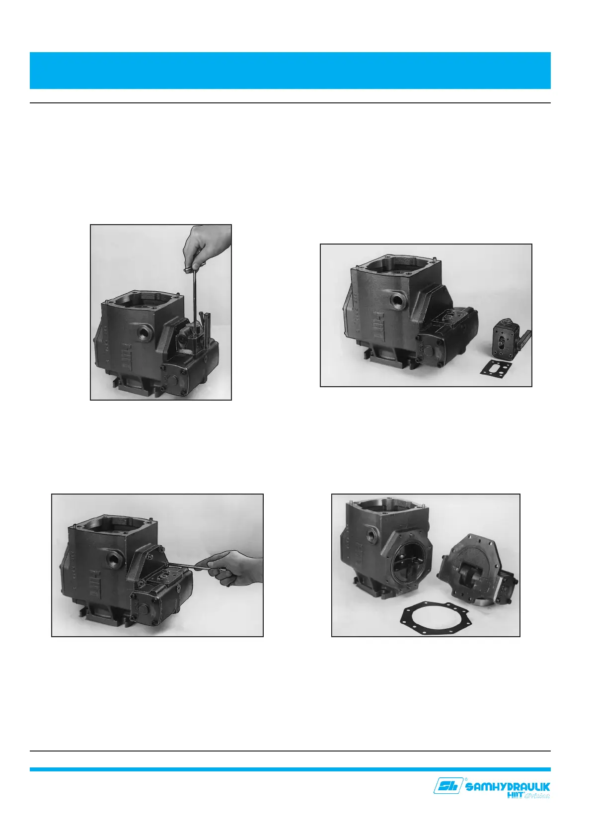
5.5.2 - Allentare ed estrarre le quattro viti di fissaggio del
regolatore (75)(fig.19), quindi togliere lo stesso
facendo attenzione a maneggiare e della spina di
centraggio (64) (fig. 20).
5.5.3 - Allentare ed estrarre le sei viti di fissaggio (75) del
coperchio/servocomando (4) (fig. 21).
5.5.4 - Togliere il coperchio/servocomando (4) facendo
attenzione non danneggiare le spine di centraggio
(66) (fig. 22).
5.5.5 - Estrarre la guida per pistone (17) del piatto oscillante
(fig. 23), ed il perno (18).
5.5.6 - Allentare ed estrarre le otto viti di fissaggio (75)
del coperchio inferiore (6) (fig. 24) facendo
attenzione a non daneggiare la sezione premi-
piatto oscillante (33) (fig. 25).
5. SMONTAGGIO E RIMONTAGGIO DELLA POMPA
5. PUMP DISASSEMBLY AND ASSEMBLY
18
5.5 CYLINDER BARREL AND PUMPING ELEMENTS:
DISASSEMBLY/REPLACEMENT
5.5.1 - To remove pump cylinder barrel (24), first follow
instructions described on chapters 5.2, 5.3, and
5.4.
5.5.2 - Unscrew and remove four fixing screws of the
control (75)(fig.19) and remove it. Take care not to
damage the dowel pin (64) (fig. 20).
5.5.3 - Unscrew and remove six fixing screws (75) of the
servocontrol (4) (fig. 21).
5.5.4 - Remove servocontrol (4), Taking care not to
damage the dowel pin (66) (fig. 22).
5.5.5 Remove the piston slide (17) of the swash plate
(fig. 23), and pivot (18).
5.5.6 Unscrew and remove eight fixing screws (75) of
the lower cover (6) (fig. 24), and remove it taking care
not to damage the swash pute pusher section (33) (fig.
25).
Fig. 19
Fig. 20
Fig. 22
Fig. 21