5. SMONTAGGIO E RIMONTAGGIO DELLA POMPA
5. PUMP DISASSEMBLY AND ASSEMBLY
15
NOTA: il cuscinetto a rulli conici è stato introdotto a caldo
con l’ausilio di un martello e di una boccola.
Nel caso di HCV 100\125 il disco bimetallico può essere
estratto senza smontare il sovracitato cuscinetto.
5.3.7 - Il disco bimetallico (96) è calettato al blocco cilindri
(24) grazie a due spine (64), le quali sono state
introdotte con un apposito battitore.
5.3.8 - Per riassemblare il tutto seguire le istruzioni da
5.3.7 a 5.3.1.
IMPORTANTE
Sostituire la guarnizione (56) ogni qualvolta si smonta il
coperchio distributore (2).
5.4 SMONTAGGIO/SOSTITUZIONE DELL’ALBERO
POMPA
5.4.1 - Per estrarre l’albero della pompa (14) è necessario
eseguire prima gli smontaggi della pompa di
sovralimentazione (5) e del coperchio distributore
(2) (vedi sezioni 5.2 e 5.3).
5.4.2 - Sfilare il giunto (28) ed il cuscinetto a rulli conici
(51) utilizzando l’apposito estrattore (fig.8,9).
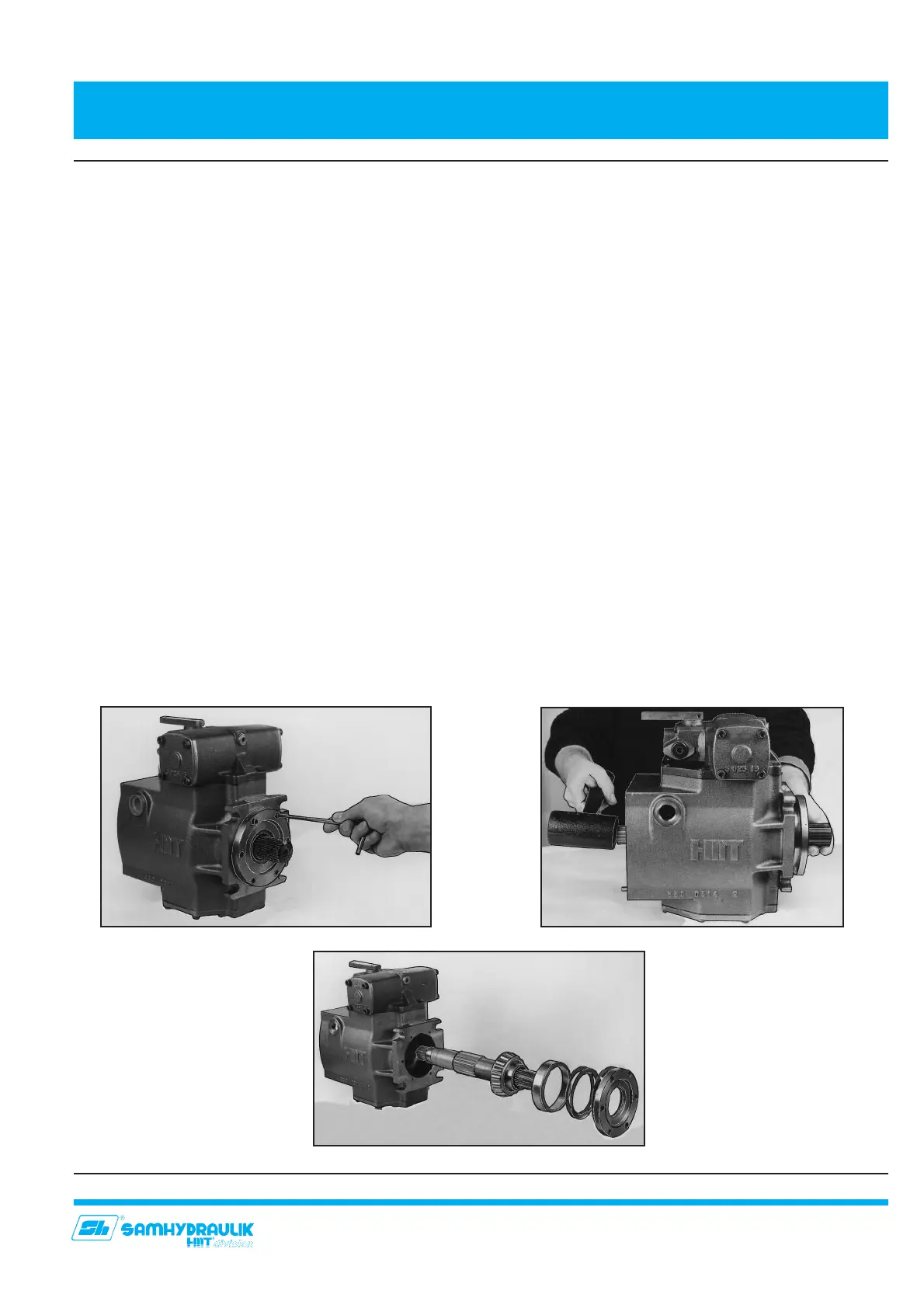
5.4.3 - Allentare ed estrarre le viti di fissaggio (69) (fig.10)
che con l’anello seeger (101), assicurano il
coperchio anteriore (7).
5.4.4 - Estrarre, con le apposite pinze, l’anello seeger (101).
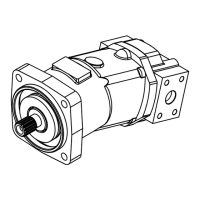
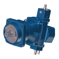
5.4.5 - Aiutandosi con un martello di plastica sfilare l’albero
(14) dalla parte anteriore completo di anello (15) con
la guarnizione (58), cuscinetto a rulli conici (50),
spessori di registro (16), guarnizione di registro (54),
anello di tenuta (53), e coperchio (7) (fig.11,12).
NOTE: tapered bearing has been heated before being
introduced by the means of a plastic hammer and a
bushing. In case of HCV 100\125, the bimetallic plate can
be removed with the rear bearing into position.
5.3.7 - Bimetallic plate is coupled (96) to cylinder barrel
(24) via two pins (64), which have been inserted
with suitable beater.
5.3.8 - In order to re-assemble all components, follow
instructions from 5.3.7 to 5.3.1.
IMPORTANT
It is raccomended to replace the gasket (56) every time
you dismount the port distributor cover (2).
5.4 PUMP SHAFT: DISASSEMBLY/REPLACEMENT
5.4.1 - To remove pump shaft (14), the disassembly of
boost pump (5) and distributor cover (2) have to
be performed: proceed as for chapters 5.2 and 5.3.
5.4.2 - Remove coupling (28) and tapered bearing (51)
using special puller (fig.8,9).
5.4.3. -Unscrew and remove fixing screws (69) (fig.10)
which, together with spring ring (15), secure the
front cover (7).
5.4.4 - Remove with appropriate pliers spring ring (15).
5.4.5 - By the means of a plastic hammer, remove shaft
(14) tapping on its rear end, together with ring (15)
with its o-ring (58), tapered bearings (50), adjusting
shims (16), adjustable seal (54), radial seal ring
(53), and cover (7) (fig.11,12).
Fig. 11
Fig. 12
Fig. 10


 To Next Page