8. SOSTITUZIONE COMANDI
Tutti i comandi delle pompe serie HCV della Samhydraulik,
a parte il rinnovato comando automotive (HNA '95) che si
avvale di una componentistica appositamente studiata,
sono perfettamente intercambiabili tra di loro mediante la
rimozione delle 4 viti che li fissano al servocomando.
Quando si sostituisce un comando con un’altro è sempre
buona regola rifare l’azzeramento idraulico del comando.
Prima di fare l’azzeramento idraulico del comando è
comunque consigliato controllare anche l’azzeramento
meccanico del servocomando, che è uguale per tutte le
pompe della serie HCV .
8.1 AZZERAMENTO MECCANICO DEL
SERVOCOMANDO
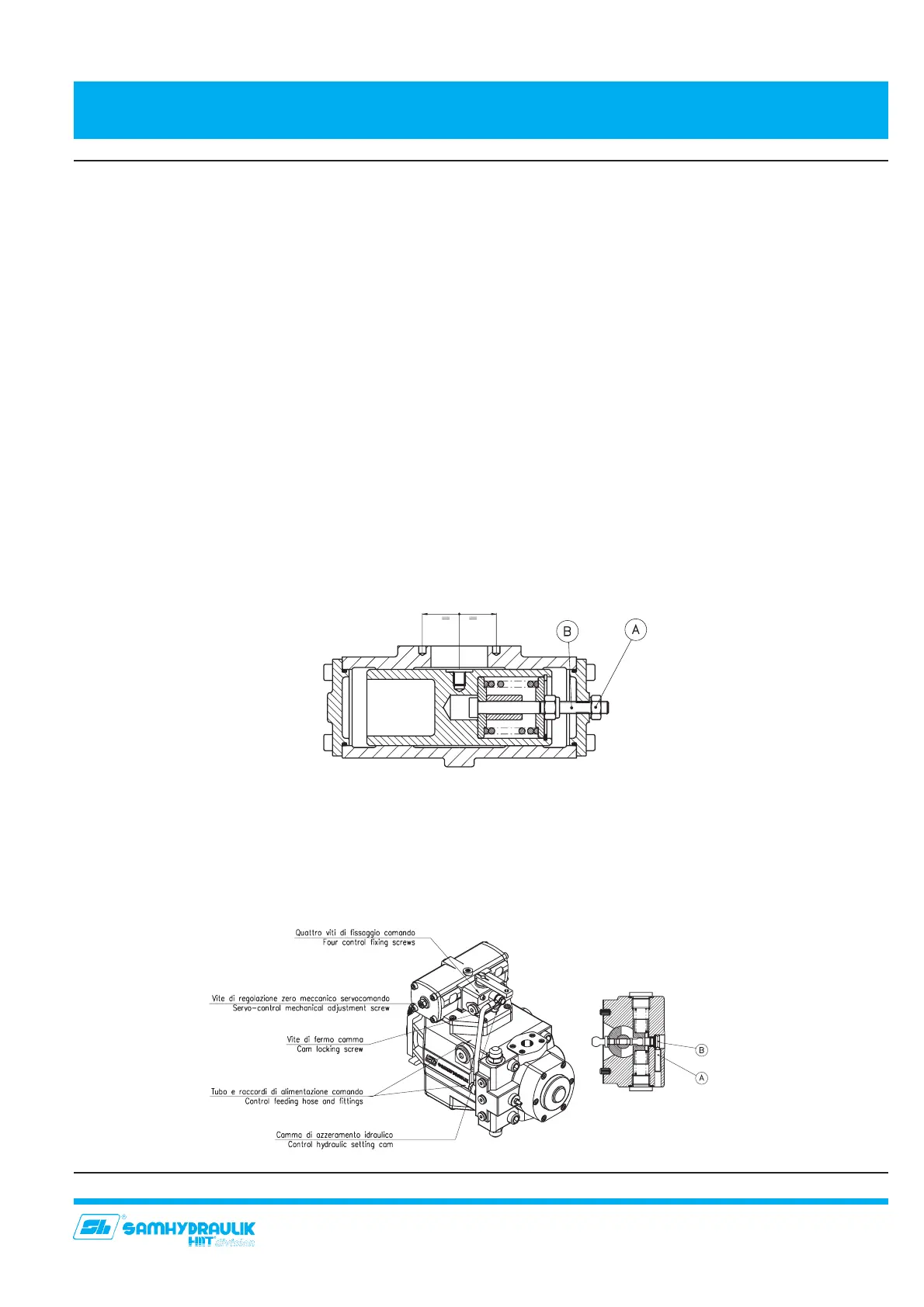
Togliere il tubo di alimentazione del regolatore e tappare
la bocca di mandata dello stesso. Azionare la pompa (senza
agire sul regolatore): la portata deve essere nulla. In caso
contrario allentare il dado (A) ed agire sul tirante (B) sino
ad ottenere portata nulla. La verifica, valida sia per
l’azzeramento meccanico che per quello idraulico, può
venire anche effettuata mettendo due manometri su GA e
GB controllando che tutti e due misurino la medesima
pressione. Rimontare il tubo di alimentazione.
Con riferimento ai sezionati dei singoli comandi:
8.2 AZZERAMENTO IDRAULICO DEL COMANDO “HL”
(MANUALE)
Allentare la vite (A) e, con un cacciavite agire sul perno
eccentrico (B), sino ad ottenere l’annullamento della portata.
Serrare il grano (A).
29
8. SMONTAGGIO SOSTITUZIONE REGOLATORI
8. CONTROLS DISASSEMBLY REPLACEMENT
8. CONTROLS REPLACEMENT
All controls of the Samhydraulik HCV pump series, except
the new automotive control (HNA '95) that is formed by
some purpose - designed special parts, are completely
interchangeable by removing four bolts that fix control to
the servocontrol.
Whenever a control is replaced it would be wise to perform
the hydraulic adjustment of the control .
Before zero-setting the hydraulic control, it is recommended
to check the mechanical adjustment of the servocontrol,
that is the same for all HCV pump series.
8.1 MECHANICAL ADJUSTMENT OF THE
SERVOCONTROL
Remove the control feed pipe and plug the feed port.
Operate the pump (do not operate on control): flow must
be zero. If the flow is not zero, unscrew nut (A) and adjust
pulling rod (B) until zero flow is reached. Testing, for
mechanical and also hydraulic zero setting, can be done
by inserting two pressure gauges on GA and GB ports.
These two manometers have to read exactly the same
pressure. Connect feed pipe.
With reference to servo control drawings:
8.2 HYDRAULIC ZERO SETTING FOR “HL” CONTROL
(MANUAL)
Release screw (A) and with a screwdriver, operate on the
eccentric link (B) until zero flow is obtained. Lock the screw
(A).


 To Next Page