EB 8384-1 EN 69
Mounting and start-up
5.14.1 Connecting the electrical
power
Risk of malfunction due to incorrect sequence
of mounting, installation and start-up.
Keep the following sequence.
1. Remove the protective caps from the
pneumatic connections.
2. Mount the positioner on the valve.
3. Connect the supply air.
4. Connect the electrical power.
5. Perform settings.
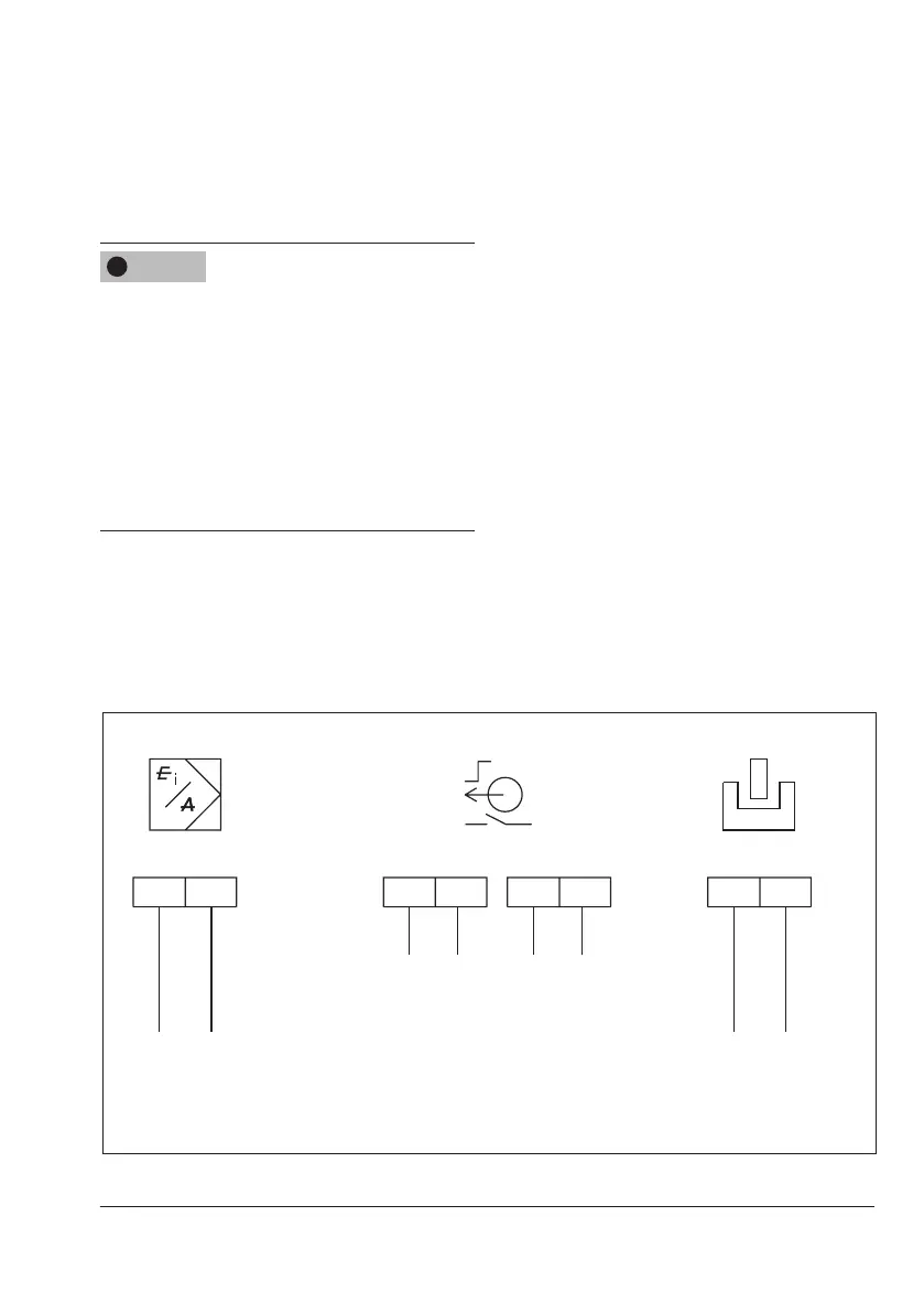
Î Connect the electrical power (mA signal)
asshowninFig.26.
5.14.2 Switching amplier
according to EN 60947-
5-6
For operation of the limit contacts, switching
ampliersmustbeconnectedintheoutput
circuit. They must comply with the limit val-
ues of the output circuits conforming to
EN60947-5-6.
Î Observe the relevant regulations for in-
stallation in hazardous areas.
For applications in safe areas (non-hazard-
ous areas), limit contacts can be directly in-
terconnected to the binary input of the PLC in
accordancewithIEC61131.Thisappliesto
the standard operating range for digital in-
putsaccordingtoClause5.2.1.2of
IEC61131-2withtheratedvoltageof
24VDC.
NOTICE
!
+11 -12 +51 -52 +41 -42
(A2) (A1)
+45 -44
Explosion-protected version Connection for switching
ampliersaccordingtoEN60947-5-6
Version without explosion protection Connection to PLC
Binary input acc. to IEC 61131-2
Limit contacts
Inductive limit contact
mA control signal
Connection for switching
amplieracc.toEN60947-5-6
Option
Fig.26: Connecting the mA control signal

 Loading...


