EB 8355-2 EN 5-5
Installation
Actuators with 175 to 750cm² effective
areas
7. Make sure that the tip of the gasket (16)
projecting from the side of the connec-
tion block (Fig.5-1, middle) is positioned
to match the actuator symbol for the ac-
tuator's fail-safe action "actuator stem
extends" or "actuator stem retracts".
If this is not the case, unscrew the three
fastening screws and lift off the cover.
Turnthegasket(16)by180°andre-in-
sert it.
Ventplug
Ventplugmustpoint
downward when the
valve is installed
Viewontothesignalpressureconnection
Left attachment Right attachment
Cover
Switchover plate
Intermediate plate (15)
Clamp (1.2)
Signal pressure borehole
175to750cm²
120cm²
Type3277
Type3277-5
Fig.5-2: Mounting the clamp
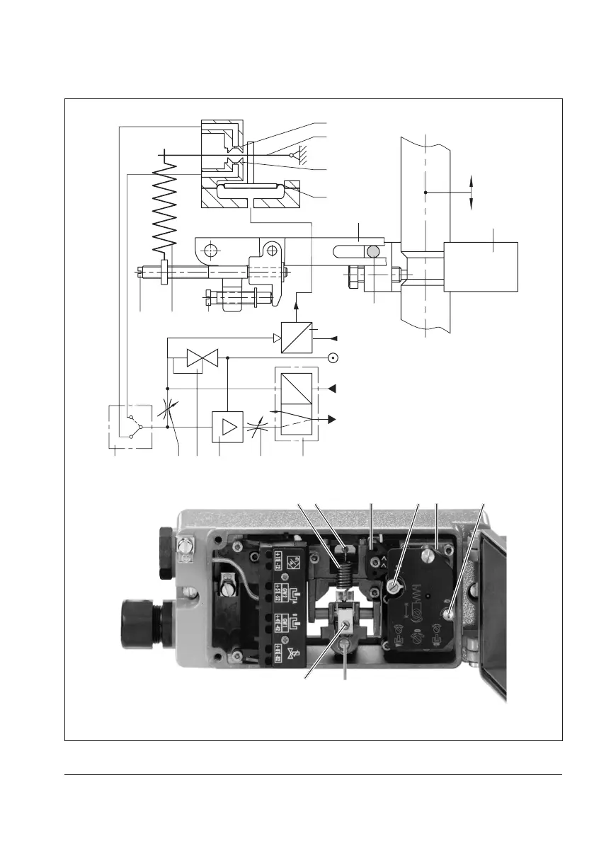
Travel
6.1
4
6.2
3
2.2
5
1
1.1
1.2
P
e
9 Supply
V
P
st
Q
Xp
p
i
mA
13
4
6.1 6.2
3 7 8 9 11
Fig.5-3: Functional diagram and inside view
 Loading...


