5-20 EB 8355-2 EN
Installation
positioner(>>or<>),thisstartingpoint
can be either the lower or upper range
value(4or20mA)ofthesetpoint.
− The set point range and thus the upper
range value determine the travel of the
valve.
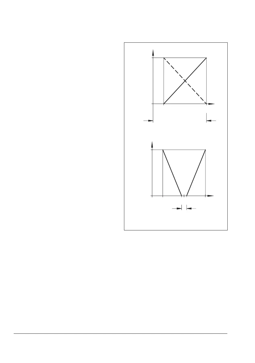
− In split-range operation (Fig.5-11, be-
low), the control valves work with smaller
set point ranges. The controller output
signal is used to control two control
valves, dividing it such that the valves
move through their entire travel range at
halftheinputsignalrangeeach(e.g.rst
valvesetto4to12mA,secondvalveset
to12to20mA).Toavoidoverlapping,
allowforadeadbandof±0.5mAas
shown in Fig.5-11.
− The starting point (zero)isadjustedat
thezeroadjuster(6.2);thespan,i.e.the
upper range value, is adjusted at the
span adjuster (6.1).
− When the positioner is controlled by a
computer whose signal is limited, e.g.
between4to20mA,setthepositioner
totherangefrom4.5to20mA.Thisis
the only way to ensure that the actuator
is completely vented and the valve com-
pletely closed when the controller issues
a4mAsignal.
Foroperatingdirection<>,settherange
to4to19.5mA.
0%
4
< >< <
Set point (input
signal)
Open
Travel
Closed
4 20 m
12
0%
< >< <
Dead band
Open
Travel
Closed
Valve2 Valve1
Fig.5-11: Normal or split-range operation
Î Connect an ammeter to the control signal
input at the terminals 11 (+) and 12 (–).
Î Connect the supply air to the supply in-
put (supply 9).
5.5.1 Air output capacity and
proportional band X
P
1. Close the volume restriction (11 in
Fig.5-3) as far as the required position-
ing speed permits.