EB 8355-2 EN 5-13
Installation
b) Mounting the intermediate
piece
SAMSON Type3278 Actuator
1. Fasten the adapter (4) to the free shaft
end of the rotary actuator.
2. Fasten the intermediate piece (2) to the
actuator housing using two screws.
Align the intermediate piece so that the
air connections of the positioner point to-
ward the diaphragm case side.
3. Alignthecamdisk(8)andscale(7)as
described in section 5.3.3 and fasten.
Actuators according to VDI/VDE3845
(09/2010), xinglevel2
1. Place the assembled intermediate piece
(2, 9, 11 and 12) onto the mounting
bracket included in the scope of actuator
delivery and fasten.
2. Alignthecamdisk(8)andscale(7)as
described in section 5.3.3 and fasten.
c) Basic setting of the cam disk
The valve model used determines the basic
setting of the cam disk.
Cam disks tailored to the special characteris-
tic of a valve cause the valve to open in a
non-linear or non-equal percentage way.
The visible difference between the set point
(4 to 20mA) and the actual position (open-
ing angle) does not constitute a system devi-
ation of the positioner.
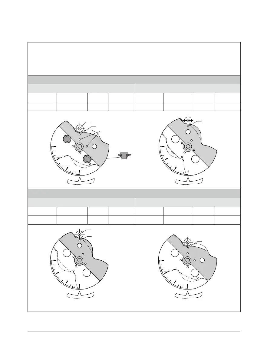
Single-acting rotary actuator with spring-return mechanism
Linear cam disk (equal percentage cam disk is represented by a broken and dotted line)
Control valve opens counterclockwise
For valves that open clockwise, the cam disk must be turned over so that lever with feeler roll moves
over the same disk segments as shown in the images below, but with the cam disk turning clockwise.
Fail-safeaction:fail-close valve
Operating direction increasing/increasing >> Operating direction increasing/decreasing <>
Set point Signal pressure Valve Characteristic Set point Signal pressure Valve Characteristic
increases increases opens N decreases increases opens I
90˚
60˚
30˚
0˚
90˚
60˚
30˚
0˚
Feeler roll
Starting point N
Starting point I
Hole to secure the cam disk
Insertclipandpresstheaps
outwards
Fail-safeaction:fail-open valve
Operating direction increasing/increasing >> Operating direction increasing/decreasing <>
Set point Signal pressure Valve Characteristic Set point Signal pressure Valve Characteristic
decreases decreases opens I increases decreases opens N
90˚
60˚
30˚
0˚
90˚
60˚
30˚
0˚
Feeler roll
Starting point N
Starting point I
Alignment at max. signal pressure
Fig.5-8: Cam disk settings for single-acting actuators
Note
 Loading...


