EB 8355-2 EN 5-11
Installation
The pin must not slip out of the bracket
once installed.
6. Check whether the correct range spring
has been installed as listed in Table 5-6.
7. Range spring 1 is installed as standard.
If necessary, replace it with range spring
2includedintheaccessoriesandxitat
the outer hook-in holes.
8. Perform positioner setting (see sec-
tion5.5).
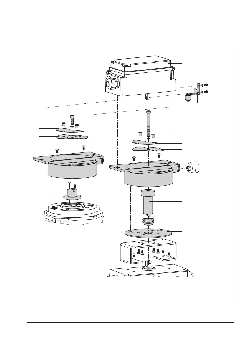
5.3.3 Attachment to rotary
actuators
Î Required mounting parts and accesso-
ries:Table5-7
Î See Fig.5-7
Attachment to rotary actuators complies with
VDI/VDE3845(September2010)require-
ments. The rotary motion of these actuators
is converted into a linear motion required by
the pneumatic control unit of the positioner
using the cam disk of the actuator shaft and
a feeler roll on the positioner lever.
Double-acting springless rotary actuators re-
quire the use of a reversing amplier on the
connection side of the positioner housing
(seesection5.3.4).
Whenusingareversingamplier,thepres-
sure regulator (9, Fig.5-3) must be turned
clockwise as far as it will go (see sec-
tion5.4.2).
1
3
7
7
8
2
4
8
2
11
12
9
10
5
Attachment according to
VDI/VDE3845
(09/2010)
Attachment
SAMSON Type3278
1 Positioner
2 Intermediate piece
3 Lever with feeler roll
4 Adapter
5 Transmission lever
6 Screws
7 Dial plate
8 Cam disk
9 Washer
10 Mounting bracket
11 Coupling
12 Gasket
Ventplugorlter
check valve
Fig.5-7: Attachment to rotary actuators