5-24 EB 8355-2 EN
Installation
The tags of the limit switches cannot be
turned by 360°. As a result, it is important to
observe the correct assignment of switches A
and B to the valve positions (valve CLOSED
and valve OPEN), especially when the limit
switches are to be connected in safety
circuits.
The required switching function, i.e. whether
the output relay is to be picked up or
releasedwhenthetagenterstheeld,must
be determined by jumpers for either load
current or no-load current at the switching
amplier.
Adjusting the switching point
Î Move the valve to the switching point
and adjust the tag by turning the adjust-
ment screw (3) so that the switching point
is reached and indicated by the LED on
theswitchingamplier.
To guarantee the switching under all am-
bient conditions, adjust the switching
pointapprox.2%beforethemechanical
stop(OPEN/CLOSED).
Note
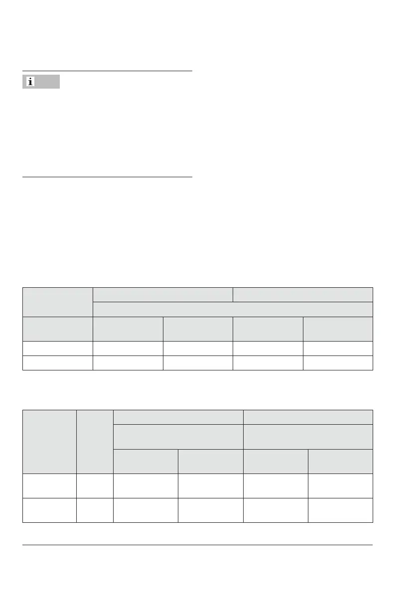
Table 5-2: Assignment of switches A and B for direct attachment to Type3277 Actuator (see
section5.3.1)
Left attachment Right attachment
Switch
Valve position Tag outside
inductive eld
Tag inside
inductive eld
Tag outside
inductive eld
Tag inside
inductive eld
Closed B A A B
Open A B B A
Table 5-3: Assignments of switches A and B with attachment according to IEC60534-6 (see
section5.3.2) and attachment to rotary actuators (see section5.3.3)
Operating
direction
Valve
position
Actuator stem extends (FA) Actuator stem retracts (FE)
Switch
Tag
Switch
Tag
Outside
inductive eld
Inside inductive
eld
Outside
inductive eld
Inside inductive
eld
>> Closed
Open
B
A
A
B
A
B
B
A
<> Closed
Open
A
B
B
A
B
A
A
B