6-1 Samsung Electronics
4321 5 6 7 8 9 10 11 12 13 14 1516
16
6. PCB Diagram and Parts List
6-1 Indoor Unit
6-1-1 Slim 1 way cassette type
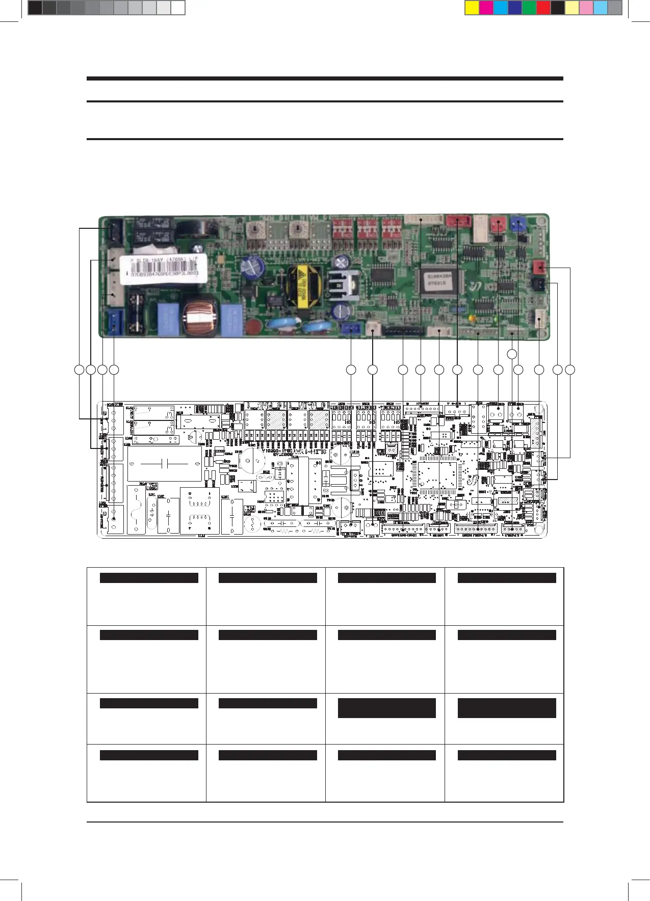
■ MAIN PCB (AVXCSH022/028/036E✳, ND022/028/0361H✳✳✳)
①
②
CN74- Drain pump
③
#1: Input Operating Capacitor Motor
#2, #4: No used
#3: Motor Control Signal
#5: N phase Boltage
④
#1: L phase
#2: N phase
⑤
#1: 5V input
#2: GND
#3: Hall IC output
⑥
#1: DC12V
#2: GND
⑦
⑧
#1~5: LED Control
#6: AUTO_S/W
#7: Remocon_Signal
#8: GND
#9: VCC
⑨
#1: DC12V
#2~5: Louver control
⑩
#1, #3: DC12V
#2: Error CHK Out
#4: Comp. CHK Out
⑪
#1: Comm. Signal F1
#2: Comm. Signal F2
⑫
#1: Comm. Signal F3
#2: Comm. Signal F4
⑬
#1: ROOM Temp. Sensor
#2: GND
#3: EVA IN Temp. sensor
#4: GND
⑭
#1: GND
#2: Float S/W
⑮
#1: On/off Contact point input
#2: GND
⑯
#1,6: DC12V
#2~5: Motor Control
#7~10: Not used
CN74 Ventilator CN74- Drain Pump CN73- Fan Motor CN71-AC Power
CN44- RPM Feedback CN32-Remocon DC12V CN10-Micom Download CN91-Display
CN60-Louver CN81-External Control Out
CN31- Indoor/Outdoor Unit
Communication
CN33- Wred Remote Controller
Communication
CN41- Temp. sensor CN51-FLOAT S/W CN83- External Control CN61, CN62-Slide Panel
$9;&6+B$BaLQGG