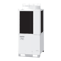
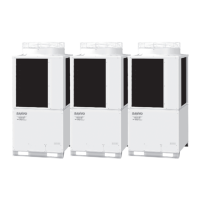
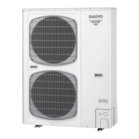
1-4
Outline of W-2Way ECO-i SYSTEM
1
2
3
4
5
6
7
8
2. Features of W-2WAY ECO-i SYSTEM
2-1. Outline of W-2WAY ECO-i SYSTEM
System example
ADDITION
CONCENTRATION
If indoor/outdoor units need servicing, a ball
valve
(
field supply
)
cuts off non-operational
units to let other units stay running.
* The capacity after the setting
must not exceed 48 PS.
Since all tubings are
concentrated into
one pipe shaft, you
can minimize piping
space and construc-
tion labor
Maximum number of combined outdoor units
Maximum horsepower of combined outdoor units
Maximum number of connectable indoor units
Indoor/outdoor unit capacity ratio
Maximum actual tubing length
Maximum level difference
(
when outdoor unit is lower
)
Maximum total tubing length
3
48 HP
40
50~130%
150m
50(40)m
300m
System limitations
CONNECTION
If your indoor capacity load
changes in the future, it’s easy to
add on both indoor and outdoor
units using the same tubing.
*If additional installation of outdoor and indoor units is
expected, the size of refrigerant tube should be decided
according to the total capacity after the addition.
Combination of outdoor units
The DC inverter unit can be used independently or in combination.
CAUTION
R407C models and R22 models must not be used in combination with each
other.
Combination of outdoor units
L
Total horse
power
8 1012141618202224262830323436384042444648
Type (hp)
81 1
10 1 12111 22111
12 1 1 1 1 1
14 1 1 1 1 1 1
16 1 1112 1112223

 Loading...


