14
Adjusting the Balance/Scale
Before you begin the adjustment procedure, let the balance/scale warm up for at least 30 minutes, and run a function
test.
Important Note:
The number(s) written next to the components, e.g., main PCB (118), refer to the exploded-view diagram on page 4.
Adjustment Sequence
Adjust the overload stops
Adjust the zero point offset value
Check the off-center load
Adjust the linearity
Calibrate the balance/scale
Opening the Balance/Scale Housing
Only if you wish to adjust the zero point offset value or the linearity will you need to open the balance/scale housing.
All tests and other tasks can be performed with the balance/scale housing left closed.
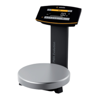
- Disconnect the balance/scale from the operating voltage and remove the
weighing pan (101).
- If the balance/scale has a rectangular weighing pan, you must first remove
the screw (103.A) along with the leaf spring for grounding (102), and the
pan support (103).
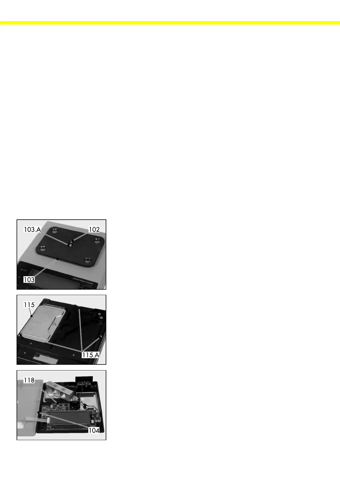
- Turn the balance/scale over and place it with the pan side facing
downward on a padded surface to prevent damage to the weighing
system.
- Remove the 3 screws that are now accessible (115.A) from the housing
base(115).
- Place the balance in the upright position; carefully remove the upper
housing section(104) and place it at the left beside the balance/scale.
- Now you can access all components located on the main PCB (118)
required for adjusting the zero point offset value and the linearity.
- Follow these steps in reverse order to close the balance/scale housing.
 Loading...