20
Linearity Data
Balance/Scale Type Weighing Capacity Linearity
PT120 - 000V1 120 g <=± 0,01 g
PT120 - 000V103 120 g <=± 0,01 g
PT210 - 000V1 200 g <=± 0,01 g
PT600 - 000V1 600 g <=± 0,1 g
PT1200 - 000V1 1200 g <=± 0,1 g
PT2100 - 000V1 2000 g <=± 0,1 g
PT6 - 000V1 6000 g <=± 1 g
GT210 - G00V1 200 g <=± 0,01 g
GT600 - G00V1 600 g <=± 0,1 g
GT1000B - G00V1 1000 g <=± 0,1 g
GT2100 - G00V1 2000 g <=± 0,1 g
Adjusting the Linearity
Note:
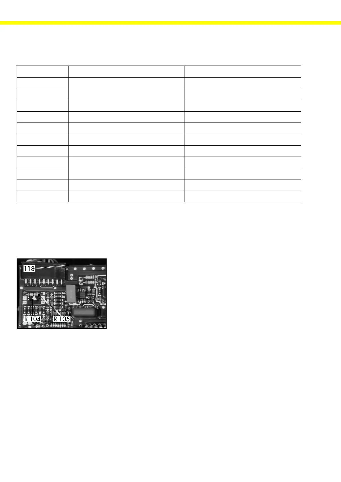
With the PT...-000V1 and GT...-G00V1 balances, negative linearity errors can be corrected with resistor R104, and
positive linearity errors can be corrected with resistor R105.
- Open the balance/scale housing (see page 14).
- Locate the position of balancing resistors R104 and R105 on the main PCB
(118) (see „Overview of the Test Points“ on page 31).
- Desolder resistor R104 or R105.
- Connect the balance/scale to the power source.
- Calibrate the balance/scale in the gross value mode (see page 24).
The linearity error is determined from the following equation:
Linearity error = actual value – set value
Definition:
The actual value thereby corresponds to the value indicated by the balance at half-load, and
the set value corresponds to one-half of the value indicated by the balance at full load.
 Loading...