SARTORIUS Portable and Gold
21
- Unload the balance/scale and tare.
- Place the entire load (calibration weight value) on the balance/scale, and
write down the value displayed.
- Unload the balance/scale and tare.
- Place one half of the load (½ calibration weight value), and write down the
value displayed.
- Determine the linearity error with the use of the equation given.
Example 1 (PT6-000V1: Half-load (actual value) +2505 g
– full load / 2 (set value) + 2502 g
= linearity error + 3 g
- Now, determine the balancing resistance from the calculated linearity error with the use of the „Table of Balancing
Resistors“ (see page 22).
- For the example 1 given (PT6-000V1 - linearity error of +3.0 g) this is a resistance value of 560 kOhm, and since
the assumed deviation is positive, this value applies to R105.
Example 2 (PT6-000V1: Half-load (actual value) +2499 g
– full load / 2 (set value) + 2503.5 g
= linearity error – 4.5 g
- For the example 2 given (PT6-000V1 - linearity error of –4.5 g) this is a resistance value of 36 kOhm, and since the
assumed deviation is negative, this value applies to R104.
Note:
Please note that the resistance values listed in the Table of Balancing Resistors are to be used as guidelines only. In
accordance with the balance/scale, it is thus possible that the next highest or next lowest resistance should be used.
- Disconnect the balance/scale from the power source.
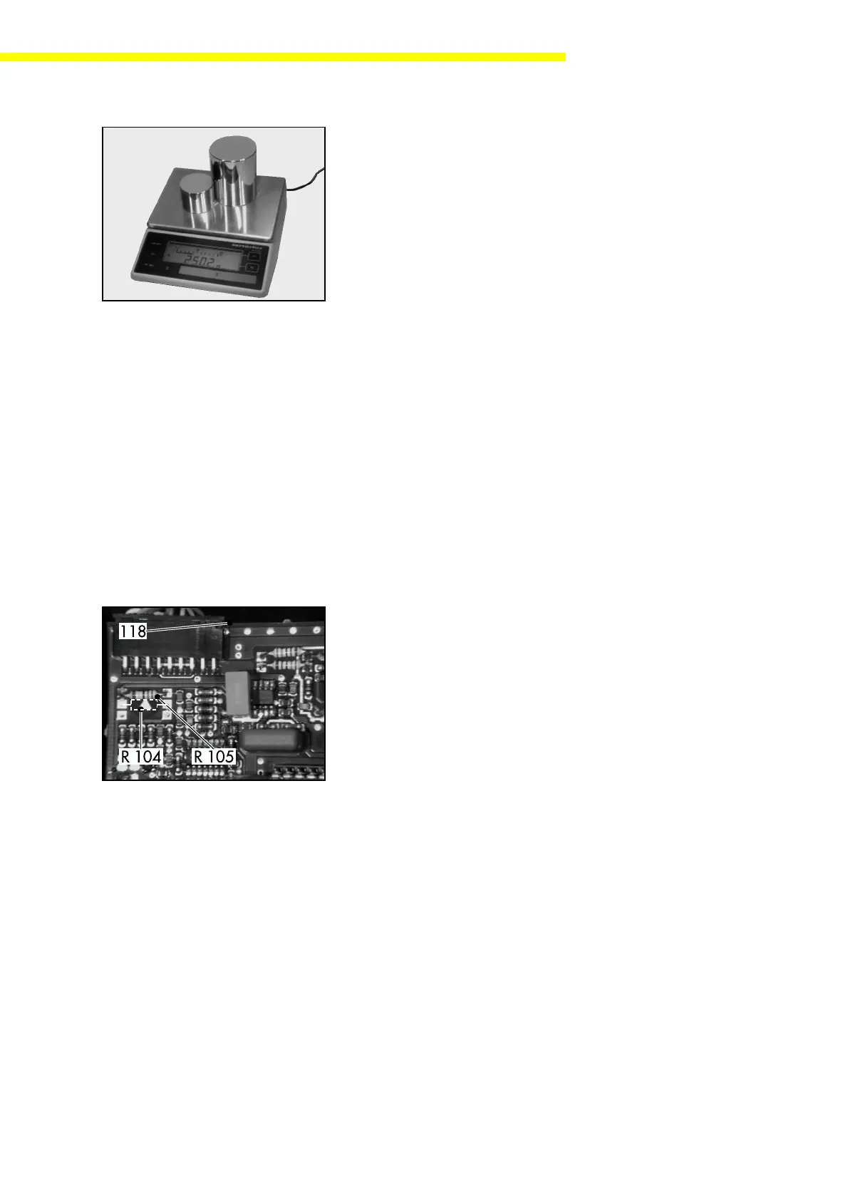
- Solder the resistor determined for negative linearity error (example 2) at
position R104, or that determined for positive linearity error (example 1) at
R105 on the main PCB (118).
- Then check the linearity again (see page 19).
- After you have adjusted the linearity, close the balance/scale housing.
 Loading...