40
Service Manual Signum
Replacing Components
Replacing the Power PCB
Warning
Disconnect the cable from the power source.
Important note:
Do not connect or disconnect live power cables to or from the equipment;
always disconnect the power cable from the wall socket (mains supply) first.
Otherwise, components could be destroyed.
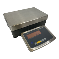
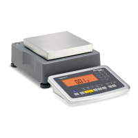
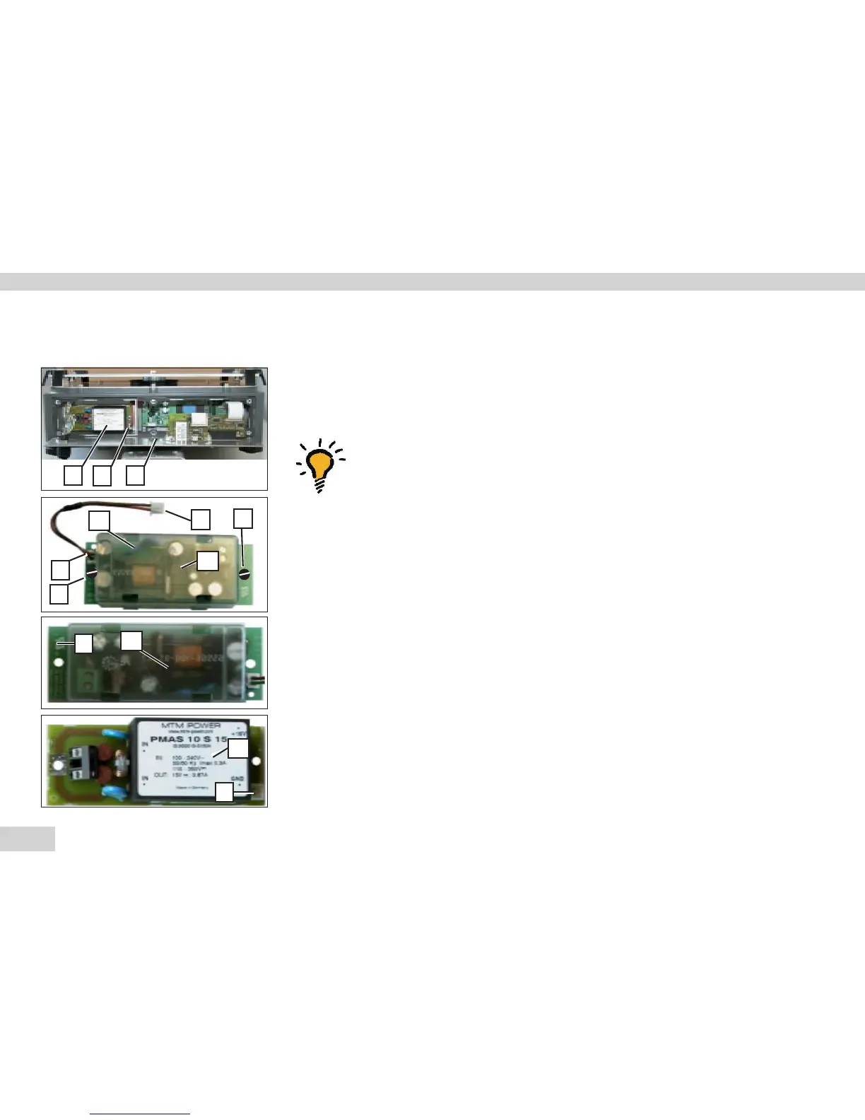
– There are three different power supply versions: (B1) 24V and (B2) 230V and (B3)
Zone 2.
– Loosen and remove six screws from the data output plate (U).
– Cut through the warranty stickers (seals).
– Fold down the data output plate (U).
– Pry the protective cap (A1) from the power PCB (B1).
To do this, insert the end of a slotted-head screwdriver into each of the four
openings on the protective cap and carefully push the retainer clips, located further
down, to one side.
– Remove the protective cap (A1) and disconnect the wire (red/brown).
– Unplug connector X, remove the 2 screws (V) and replace the power supply (B1).
– Make sure to return the protective cap to its original position.
– Apply new warranty stickers (seals) to the unit.
AUT22922a.JPG
AUT22922b.JPG
B2
!
A1
V
W
V
AUT24188.JPG
B3
AUT24186.JPG
B3
B1
X
X
X
X
U
 Loading...