41
Service Manual Signum
Replacing Components
!
AUT22916.JPG
- +
Z
AUT22917b.JPG
O1
U
O
AUT24188.JPG
Z
U
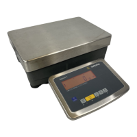
Replacing the Data Output PCB
Warning
Disconnect the cable from the power source.
Important note:
Do not connect or disconnect live power cables to or from the equipment;
always disconnect the power cable from the wall socket (mains supply)
first. Otherwise, components could be destroyed.
Different versions of this PCB (see pages 59-60) can be installed in the
unit.
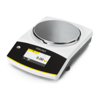
– Loosen and remove six screws (O) from the data output plate (U).
– Cut through the warranty stickers (seals).
– Remove the data output plate (U).
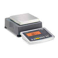
– When you replace the data output PCB (Z) make sure that the connectors are
plugged in correctly.
– If you are replacing the battery, it is imperative that you install it with the
correct polarity (+ / -).
 Loading...