Do you have a question about the Sartorius Signum 1 and is the answer not in the manual?
Information on using the manual and recommendations for efficient printing.
Explanation of symbols used in the manual for warnings and notes.
Guidelines for safe operation and repair of the scale.
Explanation of model naming conventions.
Breakdown of model code components and their meanings.
List and explanation of available scale resolutions.
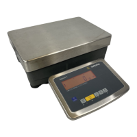
Description of the regular weighing system with strain gauge technology.
Description of the advanced weighing system with strain gauge technology.
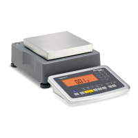
Description of the supreme weighing system with forked-lever.
Description of the supreme weighing system with forked-lever.
Description of the regular weighing system with strain gauge technology.
Description of the regular weighing system with strain gauge technology.
Details on optional tools and programs available.
Information on accompanying literature and online resources.
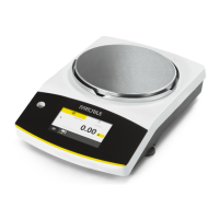
Overview of different display unit types.
Details on the flat screen display unit.
Information on the tall display unit option.
Description of component positions on the scale interface.
Explanation of various keys and their functions on the scale interface.
Diagram showing the internal components of a strain gauge scale.
Diagram showing the internal components of an EMF scale.
Step-by-step guide to activate the service mode.
Entering the service code, exiting mode, and customer code management.
Description of menu items like DATE, Code, S-DATE, MEM-NO.
Overview of calibration/adjustment functions in the number menu.
Detailed list of calibration and adjustment functions.
Options for calibration and adjustment sequences.
Steps to enter calibration and linearization weights.
Options for factory reset and menu restoration.
Procedure for external calibration using default weights.
Procedure for external calibration using user-defined weights.
Continuation of user-defined weight calibration procedure.
Procedure for calibration using an internal weight.
Procedure for external linearization using default weights.
Steps to enter the 1st and 2nd linearization weights.
Steps to enter the 3rd and 4th linearization weights.
Procedure for external linearization using user-defined weights.
Continuation of user-defined linearization weight entry.
Procedure for setting the preload weight on the scale.
Continuation of the preload setting procedure.
Procedure to clear the preload setting.
Confirmation steps for clearing the preload.
Steps to enter an external user-defined calibration weight.
Steps to enter the 1st linearization weight.
Instructions on how to open the display unit for repair.
Instructions on how to close the display unit after repair.
Procedure for replacing the front panel of the display unit.
Procedure for replacing the cable connected to the display unit.
Procedure for replacing the display PCB.
Steps for opening scales featuring strain gauge technology, noting IP ratings.
Steps for opening scales featuring electromagnetic force compensation.
Procedure for closing the scale after component replacement.
Procedure for replacing the power supply PCB.
Procedure for replacing the data output PCB.
Procedure for replacing the main PCB.
Procedure for replacing the system PCB.
Procedure to replace the power supply PCB on SIWAEDG.
Procedure to replace the main PCB on SIWAEDG.
Procedure to replace the system board on SIWAEDG.
Procedure to replace the data output PCB on SIWAEDG.
Instructions for installing the Profibus module plate.
Description of the data output plate with IP65 protection.
Configuration options for data output plates with IP44 protection.
Configuration options for data output plates with IP65 protection.
Table detailing terminal assignments for the COM1 interface.
Procedure for installing the data output cable.
List of display error codes, their causes, and solutions.
List of information messages, their causes, and solutions.
Further error and information messages with causes and solutions.
Errors related to function lock, platform connection, and required service software.
Diagram illustrating the scale's main components and their interconnections.
Description of the two sliding switches on the data output PCB.
Explanation of the menu access switch and its function.
Details on boot switch, SBI/XBPI protocol, and Close function.
Steps to configure the scale to XBPI protocol for service software.
Navigation to set COM-1 to DATPROT and BPI-232.
Table detailing SIWR models, capacities, resolutions, and tolerances.
Continuation of SIWR model specifications table.
Table detailing SIWA model types and their specifications.
Table detailing SIWAEDG model specifications.
Table detailing SIWS model types, capacities, resolutions, and tolerances.
| Readability | 0.1 g / 0.2 g |
|---|---|
| Repeatability | ≤ 0.1 g / ≤ 0.2 g |
| Linearity | ± 0.1 g / ± 0.2 g |
| Operating Temperature | +10°C to +30°C |
| Display | LCD |
| Connectivity | RS-232 |
| Calibration | External |
| Interface | RS-232 |