Chapter 2 Installation
8
2.2 Electrical Installation
) Before installation ensure that all incoming power
sources are shut OFF. Failure to observe this practice can
result in serious or even fatal injury and damage to
equipment.
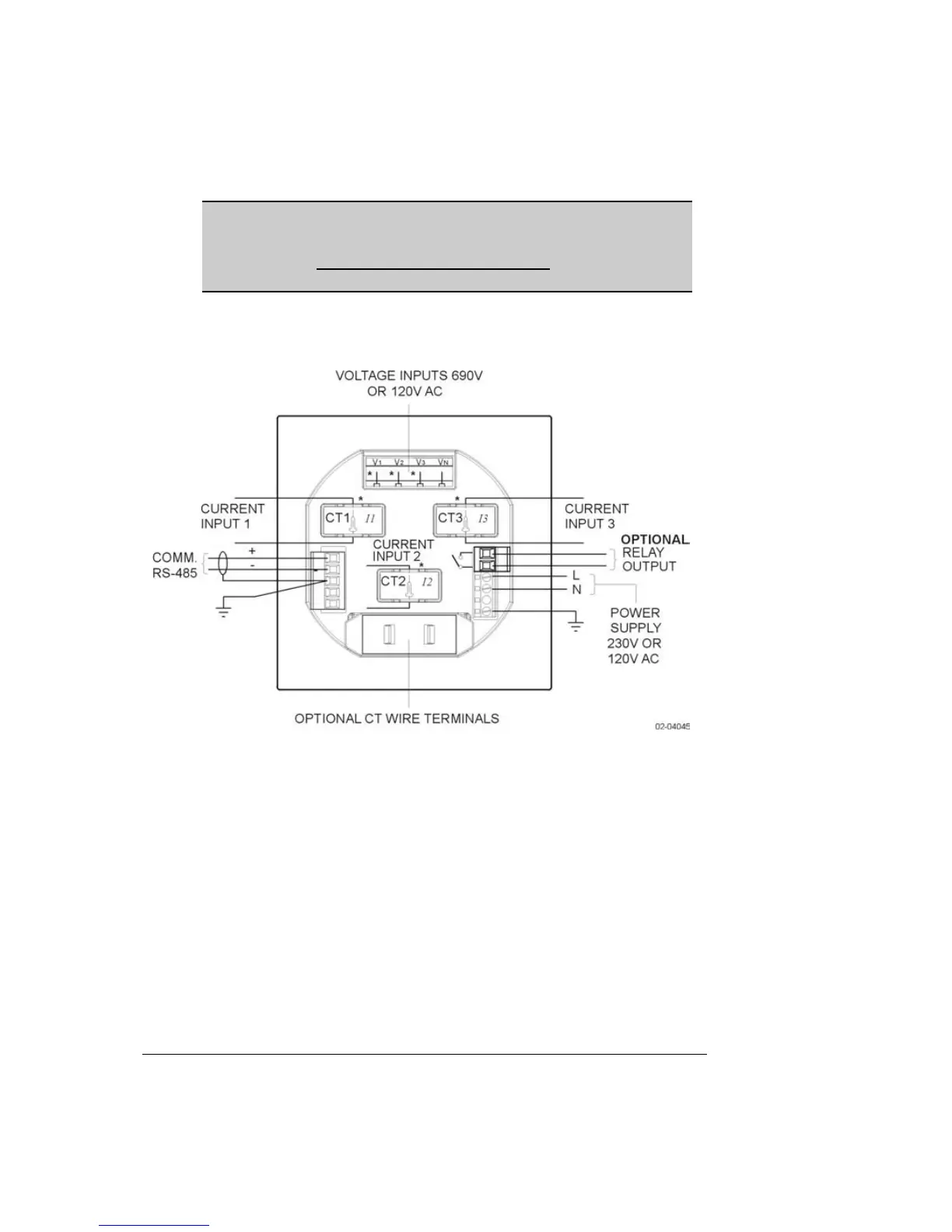
Connections to the PM130 are made via terminals (voltage input,
power supply, communication and optional relay output) and CT
cores located on the rear of the instrument as shown in Figure 2-3.
Note: If your PM130 was not ordered with the optional relay, it will
not have the relay connector.
Figure 2-3 PM130 Connections - Rear View
2.2.1 Power Supply Connection
The power supply can be dedicated-fused, or from a monitored
voltage if it is within the instrument’s power supply range.
Connection to the AC power supply is: Line to terminal L; Neutral
to terminal N.