12 Chapter 2 Installation and Interfaces
2.2.8 Analog Output
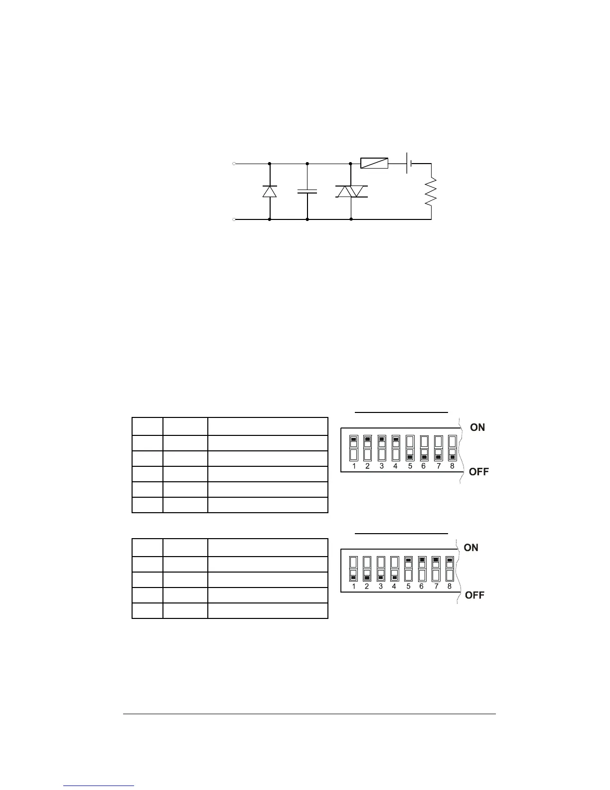
The Analog Output requires a galvanically isolated external power
supply. See Figure 2-11 for connections: negative to terminal 15 and
positive to terminal 16. In certain industrial applications, a circuit may
be required to protect against accidental shorts.
FUSE
R
D1 C1
VR1
To terminal #16
To terminal #15
D1=1N4002
C1=0.1MF/50V
VR1=250Vrms
FUSE=100mA(S.B.)
L
+
-
24V
Figure 2-11 Analog Output Connection
2.2.9 Communications
Connector Pinout
The serial interface connector is a standard D-type 9-pin plug-in,
located at the top center of the back of the instrument. Tables 2-1 and
2-2 list the pinout of the connector.
Table 2-1 RS-232 Pinout
DIP Switch Block
Pin Name Function
1 Gnd Ground (common)
2 TxD Transmit Data
3 RxD Receive Data
4 DTR Data Terminal Ready
5 DSR Data Set Ready
Table 2-2 RS-422/RS-485 Pinout DIP Switch Block
Pin Name Function
2 TxD+ + Transmit Data
3 RxD+ + Receive Data
6 TxD - - Transmit Data
7 RxD - - Receive Data
For RS-485 communications, connect together pins 2-3 (TXD+ and
RXD+), and pins 6-7 (TXD- and RXD-).
For cable drawings, refer to Appendix B.