Chapter 2 Installation and Interfaces 11
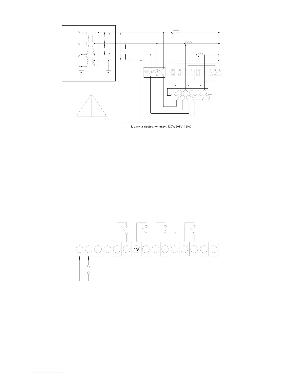
2. Line to lin e voltages: 240V; 240V; 240V.
VOLTAGES DISPLAYED:
240V
120V
240V
120V
208V
Power Transformer
delta connection
208VA C
240VA C
240VAC
N
*
*
*
120 VAC
3
120 VA C
240VA C
2
1
Shorting
Swit ches
LOAD
K
+
-
L
K
+
-
L
K
+
-
L
V
1
V
3
2
V
N
V
+
-
1
I
+
2
I
-
3
I
N
LINE 1
LINE 2
LINE 3
(A)
(B)
(C)
L
L
L
(B)
(A)
(C)
L
2
*
(B)
1
L
(A)
*
L
3
*
(C)
N
+
-
CT
7
118
46
10
12
9
1 3
25
01-01012
Figure 2-9 4-wire Grounded Delta Connection Using 3 CTs -
Wiring Mode 4L-n/4L-L
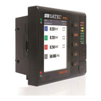
2.2.7 Relay Output Connections
Use relays #1, 2 and 4 for setpoints or KYZ pulsing. These relays do
not energize on power up.
Use relay #3 for alarm/trip setpoint. This relay energizes on power up
and de-energizes on trip condition.
Figure 2-10 illustrates wiring connections for the relays.
18 20
2221 23
01-01009-3
262524 27
15
0 ~
13 14 16 17
1
R
2
R R
3
R
4
Figure 2-10 Relay Output Connections
(Note: Power supply shown switched on)