SATEL ETHM-1 Plus 3
3 Electronics Board
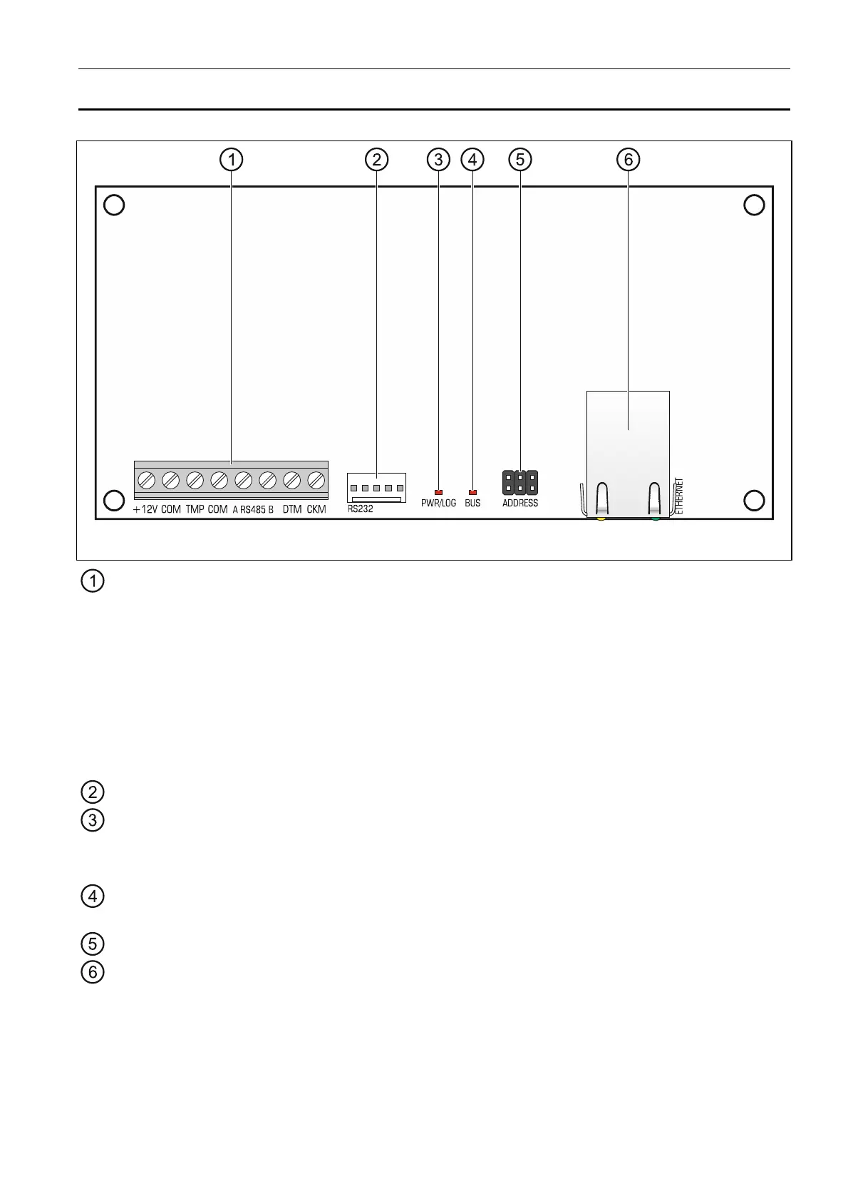
Fig. 1. Module electronics board.
terminals:
+12V - +12 V DC power input.
COM - common ground.
TMP - tamper input (NC) – if not used, it should be shorted to common ground.
A RS485 B - RS-485 port for connecting INT-GSM module. The INTG-GSM module is
supported if the ETHM-1 Plus module is connected to the INTEGRA Plus /
INTEGRA control panel with firmware version 1.18 or newer.
DTM - data (communication bus).
CKM - clock (communication bus).
RS-232 port.
PWR/LOG LED:
OK – power OK,
blinking – control panel being programmed or operated by means of the module.
BUS LED – blinking LED indicates that data exchange with the control panel is in
progress.
pins for setting the module address (see “Setting address”).
RJ-45 connector for Ethernet network. It is provided with two LEDs:
green – indicates connection to the network and data transmission,
yellow – indicates negotiated transmission rate (ON: 100 Mb; OFF: 10 Mb).