4 ETHM-1 Plus SATEL
4 Setting address
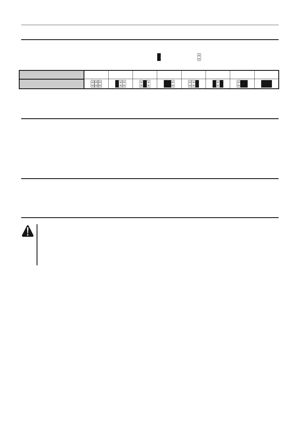
To set an address, you must place jumpers across the ADDRESS pins. Table 1 shows how
to use jumpers in order to set a specific address ( - jumper on; - jumper off).
Address
0 1 2 3 4 5 6 7
Pins status
Table 1.
4.1 Module connected to INTEGRA / INTEGRA Plus control panel
Set an address in the module within the range:
from 0 to 3, if it is connected to INTEGRA 24 or INTEGRA 32 control panel,
from 0 to 7, if it is connected to another INTEGRA or INTEGRA Plus control panel.
The address set must be different from that in the other devices connected to the keypad bus
of the control panel (the control panel does not support devices with the same address).
4.2 Module connected to VERSA control panel
Set address 4 in the module. No keypad with the address 4 may be connected to the control
panel.
5 Installation
Disconnect power before making any electrical connections.
The device is designed to be used only in the local area networks (LAN). It must
not be connected directly to the public computer network (MAN, WAN). For
establishing connection with public networks, use a router or xDSL modem.
The device is designed for installation indoors, in spaces with normal air humidity.
1. Secure the module electronics board in the enclosure. The module should be installed in
the same enclosure as the control panel. This will facilitate connecting the RS-232 ports
of control panel and module, which is required, if the control panel is to be configured via
Ethernet using the DLOADX program.
2. Set the module address (see “Setting address”).
3. Connect the +12V, COM, DTM and CKM module terminals to the control panel terminals
(Fig. 2). It is recommended that an unshielded non-twisted cable be used for making the
connection. If you use the twisted-pair type of cable, remember that CKM (clock) and
DTM (data) signals must not be sent through one twisted-pair cable. The wires must be
run in one cable.
4. If the module is to supervise the enclosure tamper switch, connect the tamper switch
wires to the TMP and COM terminals. Otherwise, connect the TMP terminal to the module
COM terminal.
5. Connect the module to the Ethernet network. Use a cable compliant with the 100Base-TX
standard (identical as for connecting the computer to the network).
6. Power on the alarm system.