SATEL ETHM-1 Plus 5
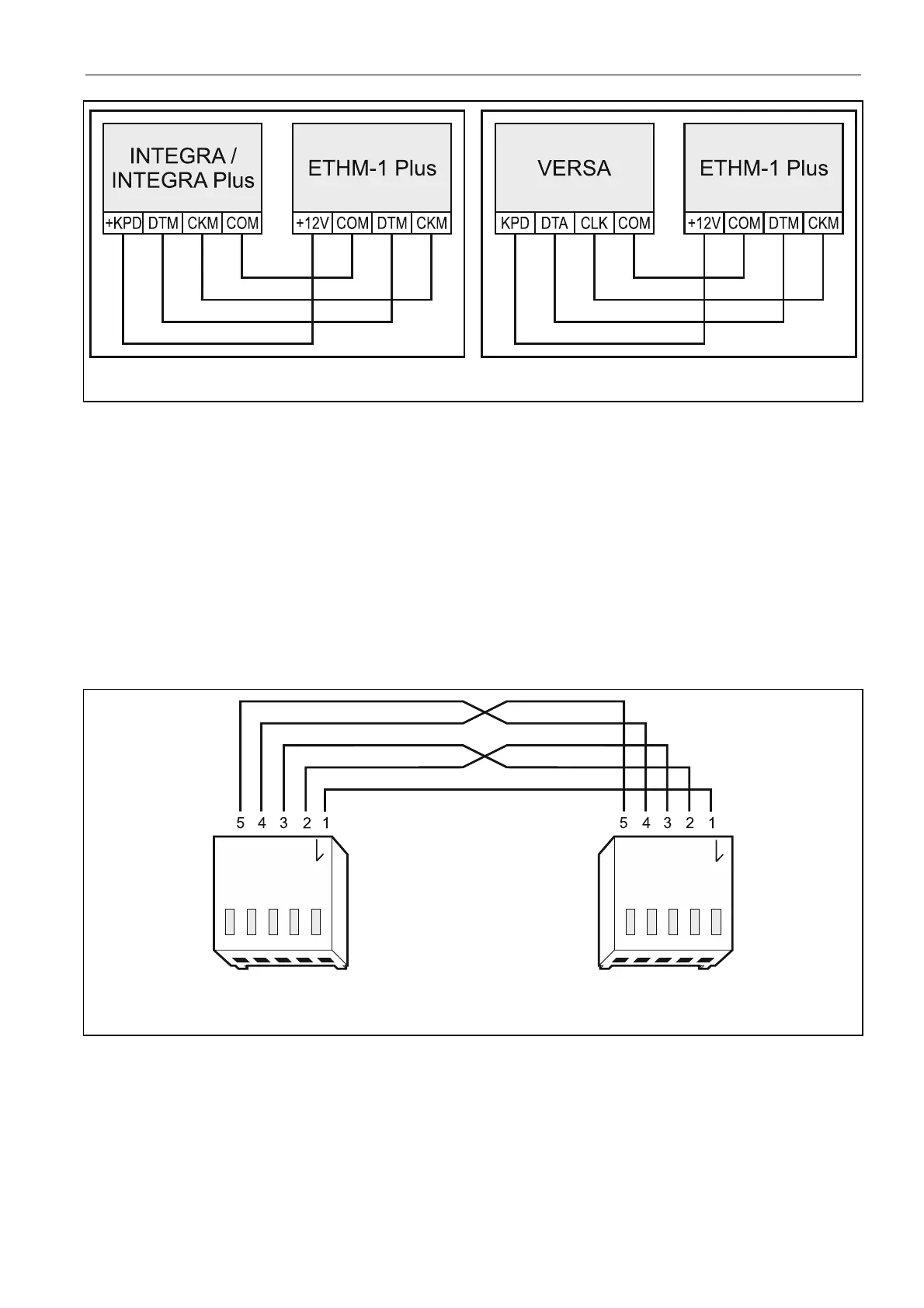
Fig. 2. Connecting the module to the control panel.
7. Start the identification function in the control panel (see the control panel installer
manual). The module will be identified as “ETHM-1” or “ETHM+GSM” (if the INT-GSM
module is connected to the RS-485 port).
8. Configure the module (see “Configuring”).
9. If the control panel is to be configured via the module using the DLOADX program,
connect the module RS-232 port to the control panel RS-232 port. Depending on the
control panel, use the following cable to make the connection:
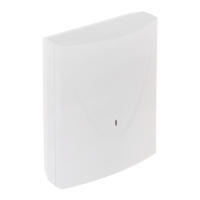
INTEGRA with connector socket of PIN5 type: PIN5/PIN5 (Fig. 3)
INTEGRA with connector socket of RJ / INTEGRA Plus type: RJ/P
IN5 (Fig. 4)
VERSA: PIN5/RJ-TTL
The above mentioned cables are available in SATEL's product offering.
Fig. 3. Wiring diagram of the cable connecting RS-232 ports of ETHM-1 Plus module and
INTEGRA control panel with PIN5 connector socket.