Section 3: Configuration and Operation
SATO D508/D512 Operator Manual Page 3-3
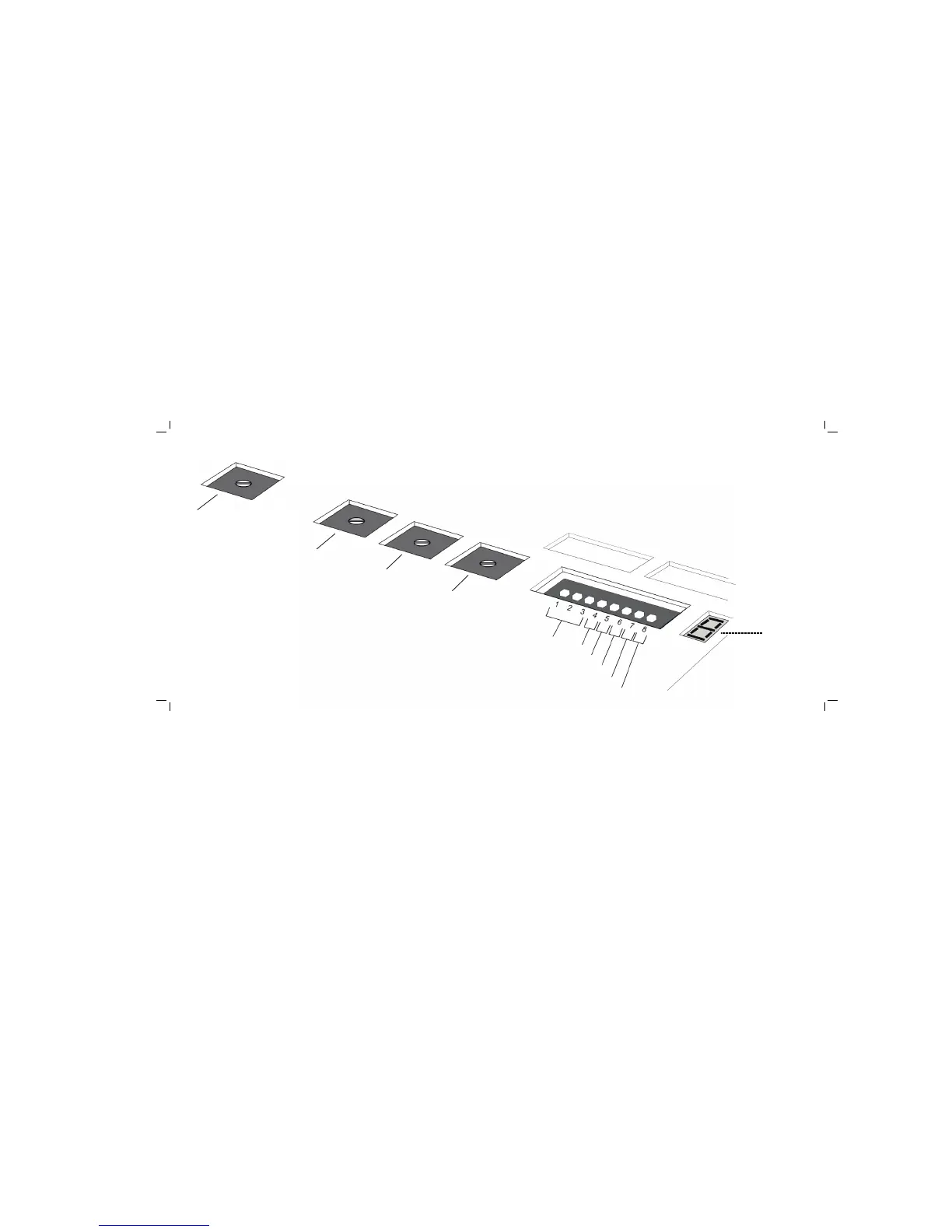
3.3 THE CONFIGURATION PANEL
The Configuration Panel is accessible when you lift up the top cover.
The panel consists of an eight-position DIP switch, four adjustment potentiometers and a seven-
segment LED Error Status display. Receptacles for connecting the optional Cutter (factory
installed) are also located on this panel.
Change and fine-tune your printer settings as required by using the mini-screw driver to turn the
potentiometers clockwise/anti-clockwise until you have the optimal adjustment position.
Do not touch VR2 and VR3. They are reserved for professional adjustments and for a trained
service person only.
DIP SWITCH SETTINGS
This is an eight-position switch used for setting the operating conditions of the printer. Switches 1
to 3 act as control for both paper handling and the loading of programs or fonts into the printer.