Section 4: Accessories Installation
M84Pro Service Manual PN: 9001111A Page 4-5
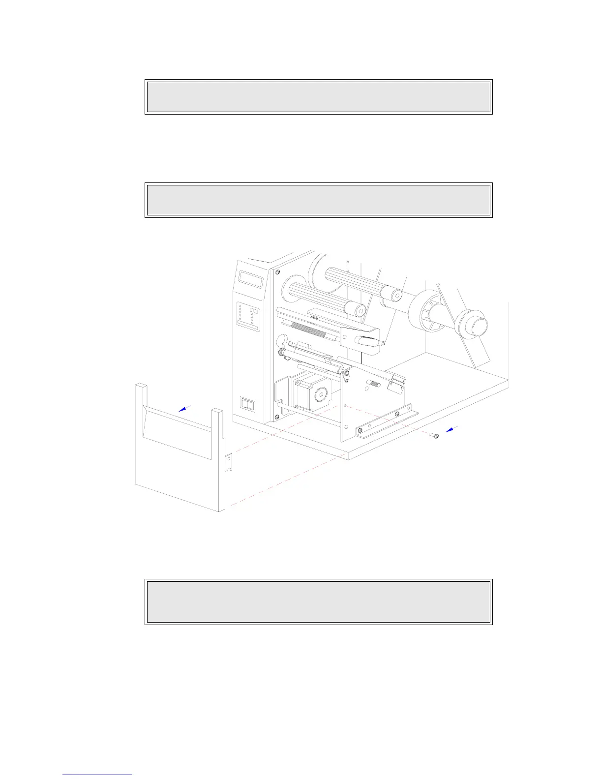
3 Remove the ribbon and label stock if applicable and leave the print head open.
4 Remove screw (1, Figure 4-2a) securing front cover (2) to the printer frame. Lift away front
cover (2).
Figure 4-2a, Dispenser Installation
5 Route dispenser wiring harness (3) through the slot in the printer side wall.
NOTE: Figures 10-1, 10-2, and 10-3 in the Diagrams & Schematics section
provide guidance on housing cover, media, and ribbon removal respectively.
NOTE: The screws are accessible at the rear of the cover on the right side.
Manipulate the cover upward and outward to remove.
CAUTION: WHEN ROUTING THE WIRING HARNESS, ENSURE THAT IIS
ROUTED IN A MANNER SO AS TO PREVENT PINCHING OR
INTANGLEMENTS.
1
2