20 Technical data
Operating Manual Linear ACTUSAFE CMFS(L)
OM-ENGLISH-Failsafe-Linear-16xx-V2.00-2022.03.03
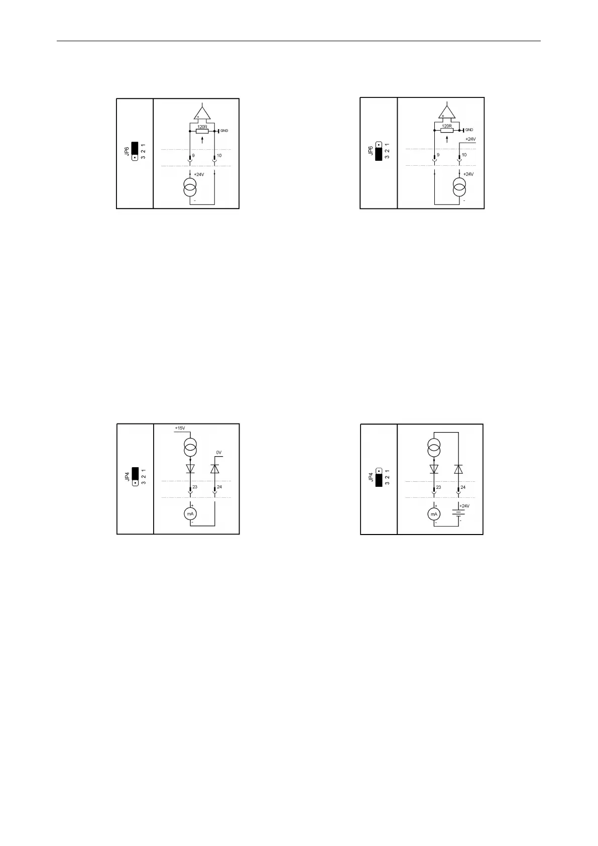
Jumper JP6 can be used to switch analog input 2 from a passive input (default) to an input with internal 24 V power supply
(for 4. . . 20 mA, two-wire transmitters).
Figure 97: Passive input (default) Figure 98: Input with internal suppy (active input)
NOTE: The analog input 2 is referenced to common of the electronic system and the auxiliary power supply (see section
20.5).
20.4 Analog output
Current range: . . . . . . . . . . . . . . . . . . . . . . . . . . . . . . . . . . . . . . . . . . . . . . . . . . . . . . . . .0. . . 20.8 mA
Resolution: . . . . . . . . . . . . . . . . . . . . . . . . . . . . . . . . . . . . . . . . . . . . . . . . . . . . . . . . . . . . 12 bit
Accuracy: . . . . . . . . . . . . . . . . . . . . . . . . . . . . . . . . . . . . . . . . . . . . . . . . . . . . . . . . . . . . . 0.5%
Max load: . . . . . . . . . . . . . . . . . . . . . . . . . . . . . . . . . . . . . . . . . . . . . . . . . . . . . . . . . . . . . 600 Ω
The analog output is galvanically isolated from the rest of the electronic system.
Jumper JP4 can be used to switch the analog output from an active power source (default) to a current sink, allowing the
output to simulate a 4. . . 20 mA, two-wire transmitter.
Figure 99: Current source Figure 100: Current sink
Ground potential is the potential of the control unit and the auxiliary supply (see chapter 20.5).
20.5 Auxiliary voltage input and output
Input voltage range (auxiliary voltage input): . . . . . . . . . . . . . . . . . . . . . . . . . . . 20. . . 30 VDC
Maximum current consumption (auxiliary voltage input): . . . . . . . . . . . . . . . .500mA
Maximum current consumption in power-save mode . . . . . . . . . . . . . . . . . . . 120 mA
(auxiliary voltage input):
Output voltage (auxiliary voltage output): . . . . . . . . . . . . . . . . . . . . . . . . . . . . . . typ. 23 V
Maximum output current (auxiliary voltage output): .. . . . . . . . . . . . . . . . . . . .200 mA
Resistance of common ground vs. earth: . . . . . . . . . . . . . . . . . . . . . . . . . . . . . . typ. 500 kΩ
Resistance of common ground vs. earth (floating version): . . . . . . . . . . . . . > 10 MΩ
Capacitance of common ground vs. earth: . . . . . . . . . . . . . . . . . . . . . . . . . . . . . typ. 100 nF
Maximum allowed voltage of common ground vs. earth: . . . . . . . . . . . . . . . max. 40 Vs
Fuse (Fuse FL1, see picture 86, page 81): . . . . . . . . . . . . . . . . . . . . . . . . . . . . .1 A slow
(Littelfuse 454 NANO
2
Slo-Blo
®
)
Ground potential is the common ground of the controller and the analog inputs and outputs.
The auxiliary voltage output can be set in menu P6.5 (see section 7.5, page 44).
86